final ch 6-8 upload - ECM
advertisement
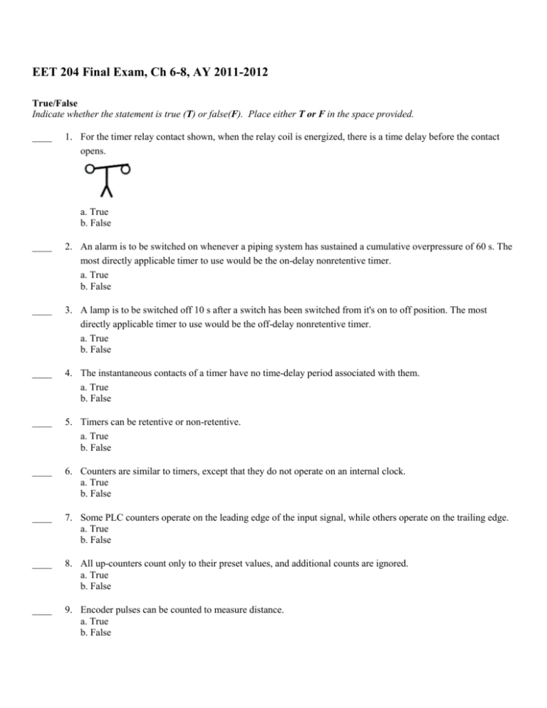
EET 204 Final Exam, Ch 6-8, AY 2011-2012 True/False Indicate whether the statement is true (T) or false(F). Place either T or F in the space provided. ____ 1. For the timer relay contact shown, when the relay coil is energized, there is a time delay before the contact opens. a. True b. False ____ 2. An alarm is to be switched on whenever a piping system has sustained a cumulative overpressure of 60 s. The most directly applicable timer to use would be the on-delay nonretentive timer. a. True b. False ____ 3. A lamp is to be switched off 10 s after a switch has been switched from it's on to off position. The most directly applicable timer to use would be the off-delay nonretentive timer. a. True b. False ____ 4. The instantaneous contacts of a timer have no time-delay period associated with them. a. True b. False ____ 5. Timers can be retentive or non-retentive. a. True b. False ____ 6. Counters are similar to timers, except that they do not operate on an internal clock. a. True b. False ____ 7. Some PLC counters operate on the leading edge of the input signal, while others operate on the trailing edge. a. True b. False ____ 8. All up-counters count only to their preset values, and additional counts are ignored. a. True b. False ____ 9. Encoder pulses can be counted to measure distance. a. True b. False ____ 10. Counters can count past their preset values. a. True b. False Multiple Choice Identify the one choice that best completes the statement or answers the question and place your answer in the space provided.. ____ 11. In the hardwired relay control circuit shown, when the switch is closed, CR coil is: a. b. c. d. ____ 12. ____ 13. A proximity switch can be actuated: a. without any physical contact. b. by a change in light intensity. c. d. by a change in capacitance. by all of the these. c. d. limit switch. proximity switch. c. overload relay coil. The symbol shown is that for a: a. b. ____ 14. energized, and the red and green lights are both on. de-energized, the red light is off, and the green light is on. energized, the red light is on, and the green light is off. energized, the red light is off, and the green light is on. pressure switch. temperature switch. The symbol shown is that for a: a. solenoid valve. b. motor starter coil. d. overload relay contact. ____ 15. A(n) ____converts light energy directly into electric energy. a. LED c. solar cell b. phototransistor d. photoconductive cell ____ 16. Fiber optic sensors: a. are not affected by electrical interference b. carry light signal signals c. use a flexible cable containing tiny fibers d. all of these ____ 17. Bar code scanners are used primarily for: a. data collection c. pressure measurement b. temperature measurement d. flow measurement ____ 18. A(n) ___ operates by sending sound waves toward a target and measuring the time it takes for the pulses to bounce back. a. pressure sensor c. ultrasonic sensor b. bar code scanner d. flowmeter ____ 19. The sensor illustrated is a: a. b. thermocouple turbine flow meter c. d. strain gauge load cell retroreflective sensor ____ 20. A tachometer normally refers to a(n) ____ used for speed measurement. a. load cell c. ultrasonic sensor b. capacitive proximity sensor d. small generator ____ 21. An encoder is used to: a. encode signals from a scanner b. c. d. decode signals from a scanner change DC to AC convert motion into a digital signal ____ 22. An actuator is a device that: a. changes AC to DC b. changes DC to AC c. converts an electrical signal into mechanical movement d. converts mechanical movement into an electrical signal ____ 23. The purpose of the M contact shown in the circuit is to a. b. c. d. open the circuit in the case of a motor overload. start the motor from a remote location. keep the starter coil energized when the start button is released. keep the starter coil de-energized when the start button is released. ____ 24. The electromagnetic latching relay: a. is used to lock in a condition b. uses a latch coil to set and hold the relay in the latched position. c. uses an unlatch coil to disengage the mechanical latch. d. all of these. ____ 25. For the programmed latching operation shown, which two instructions must have the same address? a. ON and OFF inputs. c. ON input and latch output b. ____ 26. d. OFF input and unlatch output When LS1 is actuated and LS2 is not: a. b. ____ 27. latch and unlatch outputs pilot light PL1 (O:2/5) is ON. pilot light PL2 (O:2/6) is ON. c. d. pilot light PL3 (O:2/7) is ON. all of these. When both LS1 and LS2 are not actuated: a. b. PLC program rung 1 is False. PLC program rung 2 is True. c. d. pilot light PL2 (O:2/6) is ON. all of these. ____ 28. In the hardwired circuit shown, the light will stay on: a. b. c. d. as long as S1 is closed. for 5 s after coil TD is energized. for 5 s after coil TD is de-energized. both a and c. ____ 29. Which one of the following timer parameters represents the value that increments as the timer is timing.? a. Accumulated time. c. Timer address. b. Preset time. d. Time base ____ 30. For the timer program shown, output B is switched ON when: a. b. c. d. power is applied. input A is closed. the timer is accumulating time. the accumulated value equals the preset value. ____ 31. For the timer program shown, output C is switched ON when: a. b. c. d. power is applied. input A is closed. the timer is accumulating time. the accumulated value equals the preset value. ____ 32. For the timer circuit shown, the timer accumulated value will reset to zero whenever: a. input A switch is opened. b. input A switch is closed. c. the DN bit is set to 1. d. the EN bit is set to 1. ____ 33. For the timer table shown, bit level addressing is used for: a. b. c. d. EN, TT, PRE and ACC EN, TT, and DN PRE, ACC, TT and EN PRE and ACC ____ 34. For the programmed timer circuit shown, the ____ bit of the timer functions similar to a timed contact. a. b. c. d. DN EN PB1 PB2 ____ 35. The main difference between a TON and TOF timer is that the: a. TON timer can maintain its accumulated time on loss of power or logic continuity. b. TOF timer can maintain its accumulated time on loss of power or logic continuity. c. TOF timer begins timing when logic continuity to the timing rung is lost. d. TON timer begins timing when logic continuity to the timing rung is lost. ____ 36. When addressing an RES instruction, it must be addressed to: a. a TOF instruction. b. a TON instruction. c. any address other than the of the RTO instruction. d. the same address as that of the RTO instruction. ____ 37. For the program shown, the timer starts timing when: a. b. c. d. PB1 is closed. PB2 is closed. both PB1 and PB2 are closed. either PB1 or PB2 is closed. ____ 38. For the program shown, the timer accumulated time is set to zero anytime: a. b. c. d. PB1 is closed. PB2 is closed. PB1 is open. PB2 is open. ____ 39. For the programmed timers shown, the output of timer T4:5 : a. b. c. d. turns on after a 10-s time delay and remains on. turns off after a 2-s time delay and remains off. turns on after a 3-s time delay and remains on. is pulsed on and off at 1-s intervals. ____ 40. Which instruction can best be used to turn an output coil on or off after the rung has been false for a desired time? a. RTO c. ONOF b. TON d. TOF ____ 41. The PLC counter instruction is similar to the: a. internal relay instruction. b. transitional contact instruction. c. relay coil and contact instruction. d. timer instruction. ____ 42. When the up-counter reset is set to true, the following happens: a. the preset value is set to 0. b. the preset value increments. c. the accumulated value is set to 0. d. the accumulated value is set to maximum. ____ 43. The accumulated count of a CTD counter: a. increments with each true-to-false transition. b. decrements with each true-to-false transition. c. decrements with each false-to-true transition. d. increments with each false-to-true transition. ____ 44. Which instruction, when true, will preset the counter to a count of zero? a. Enter switch input. b. Exit switch input. c. Reset input. d. Lot Full Light output. ____ 45. The counter program shown is designed to: a. b. c. d. count up and count down. record the time of an event. count beyond the maximum count allowed per counter. count below the maximum count allowed per counter. ____ 46. Output PL will be energized when: a. b. c. d. the accumulated value of C5:0 reaches 32,000. counter C5:0 is reset. the accumulated value of C5:1 reaches 32,000. the accumulated value of C5:0 and C5:1 reaches 32,000. ____ 47. If you wanted output PL to go on after a count of 40,000, you would change the preset count of C5:1 to: a. 9,999. b. 6,000. ____ 48. When input PB2 is actuated: c. 8,000. d. 12,000. a. output PL is switched off. b. counter C5:0 is reset. c. counter C5:1 is reset. d. all of these! ____ 49. For the 24-hour clock program, Counter C5:0 is preset for: a. 12. b. 24. c. 60. d. 120. ____ 50. For the 24-hour clock program, assume the accumulated count of Counter C5:1 is 14 and that of C5:0 is 10. The correct time of day would be: a. 2:10 p.m. b. 10:14 a.m. c. 10:14 p.m. d. 2:10 a.m.
