saturn sa-3350 - Highlight Industries
advertisement
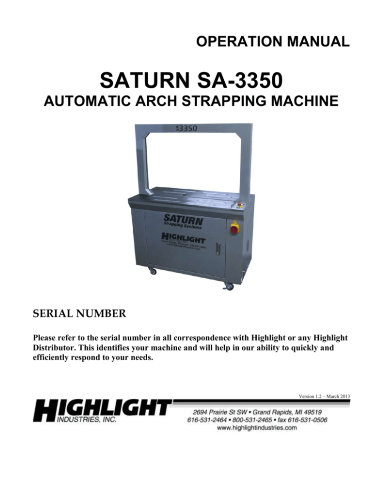
OPERATION MANUAL SATURN SA-3350 AUTOMATIC ARCH STRAPPING MACHINE SERIAL NUMBER Please refer to the serial number in all correspondence with Highlight or any Highlight Distributor. This identifies your machine and will help in our ability to quickly and efficiently respond to your needs. Version 1.2 – March 2013 TABLE OF CONTENTS 1. General System Information 1. System Specifications ……………………………………………………………………... I-1 2. Dimensional Drawing …………………………………………………………………… I-2 3. System Descriptions…..……………………..…………………………….………………. I-3 4. Limited Warranty …………………………………………………………………..……. I-4 2. Installation Instructions 1. Machine Placement ………...…………………………………………………………….. II-1 2. Machine Set-Up…..……………………..………………………………………………… II-2 3. Operation Instructions 1. Safety Precautions…………...…………………………………………………………….. III-1 2. Pre-Operation Adjustments…………………………………………………………….... III-3 3. Operator Panel…..……………………………...………………………………………...... III-11 4. Strap Threading Procedure & Diagram ..……………………………………………… III-13 5. Machine Operations……………………………………………………………………… III-14 4. Maintenance 1. Preventive Maintenance…………...……………………………………………………… IV-1 5. Troubleshooting 1. Troubleshooting Guide……………………………………………………………………. V-1 6. Electrical References 1. Electrical Schematic………………………………………………………….…………… VI-1 7. Mechanical References 1.Mechanical Parts List and Prints…………………………………………………….……. VII-1 8. Notes 1 Chapter I. Chapter 1 HIGHLIGHT INDUSTRIES, INC. Saturn® SA-3350 Arch Strapping Machine Operation Manual General System Information SATURN SA-3350 STRAPPING MACHINE OPERATION MANUAL SYSTEM SPECIFICATIONS Highlight’s Saturn SA-33550 arch strapping machine is the simplest and most user friendly arch strapping system, capable of cycle speeds of up to 30 straps per minute. The model SA-3350 was specifically designed to eliminate common problems with strapping machines and provide trouble free use for operators at an economical price. The machine takes just minutes to learn to use: align the product to the center of the arch and trigger the start button. The machine will tension, heat seal and secure your products by applying an adjustable force from 5 pounds to 120 pounds using economical 3/8” (9mm), ½” (12mm), or 5/8” (15mm) wide polypropylene strapping. The SA-3350 is designed to operate semi-automatically with the push-activated start button or by remote foot switch for hands-free use. Also, a built-in sensor in the table top allows completely automatic operation for ease of performing rapid successive straps on long products or to execute quick four-sided strapping on boxes for extra security. Value added features included in the design are: safe internally enclosed strap coil with easy loading via slide out door, easy access strap threading, automatic strap reset, auto strap loop eject when a cycle is accidentally triggered, anti-jam protection, electronic tension control, and flip-open table tops for easy cleaning & maintenance. Machine Size o o o o 22” L (front to back) x 43.5” W x 58” H Shipping weight – 400 lbs on a pallet Strap Roll Inner Diameter: 8” & 9” Adjustable Strap Width: 3/8”, ½”, 5/8” Adjustable (metric equivalents: 9mm, 12mm, 15mm) Operation Space o 24” L (front to back) x 70” W x 70” H Electrical Data o 120 VAC; Single Phase, 4 Amps, 60 Hz Production Capacity o o o o o Operating Rate: Up to 30 straps per minute, 5 - 120 lbs tension capacity Minimum Load Size: 3” L x 3” W x 0.5”H Minimum Load Weight: N/A (operator must hold down light weight packages) Maximum Load Size: 33” W x 23” H Maximum Load Weight: 45 lbs HIGHLIGHT INDUSTRIES, INC. * 2694 PRAIRIE SW; WYOMING; MI 49519 * 1-800-531-2465 I-1 SATURN SA-3350 STRAPPING MACHINE OPERATION MANUAL DIMENSIONAL DRAWING SATURN SA-3350 STRAPPER w/ 33”W x 23”H ARCH HIGHLIGHT INDUSTRIES, INC. * 2694 PRAIRIE SW; WYOMING; MI 49519 * 1-800-531-2465 I-2 SATURN SA-3350 STRAPPING MACHINE OPERATION MANUAL SYSTEM DESCRIPTIONS Arch Assembly Cabinet Assembly Strapping Head Assembly Pool Feed Unit Strap Dispenser & Brake Unit (strap) Strap Pool Chamber Holding Gripper Welding Press End Gripper Seal Plate Strap Guide Feed Rollers & Guides Tension Rollers Cam (6) Brake Timing Arch Track Holding Gearmotor Opening Gripper Cam Cam (1) Seal Plate Cam (2) Welding End Press Gripper Cam (2) Cam (5) Heater Cam (4) HIGHLIGHT INDUSTRIES, INC. * 2694 PRAIRIE SW; WYOMING; MI 49519 * 1-800-531-2465 Home Cam Cam (6) One-Way Roller Backfeed Position Cam I-3 SATURN SA-3350 STRAPPING MACHINE OPERATION MANUAL LIMITED WARRANTY Highlight Industries, Inc. warrants our Saturn Strappers, will be of merchantable quality, free from defects in material and workmanship as determined at the date of shipment, by generally recognized, applicable and accepted practices and procedures in the industry, for a period of six (6) months from the Highlight invoice date, under normal use and service. When the Purchaser gives Highlight written notice of any alleged defect within the applicable warranty period, Highlight will, at its option repair or replace the same free of charge F.O.B. its manufacturing plant, installation not included. Equipment replaced under the warranty shall have the same warranty as new equipment but does not extend the warranty of the original equipment. Satisfaction of this warranty, consistent with other provisions herein, will be limited to the replacement or repair or modification of, or issuance of a credit for, the equipment involved, at Highlight’s option. Highlight neither assumes nor authorizes any person to assume for it any other obligation in connection with the sale of Highlight’s equipment. This warranty shall not apply to any equipment which has been repaired or altered by un-authorized personnel in any way so as to, in the judgment of Highlight, affect serviceability, or which has been subjected to misuse, negligence, accident, or to equipment made by Highlight which has been operated in a manner contrary to Highlight’s instructions. In no event regardless of the cause, shall Highlight be liable for penalties or penalty clauses of any description or any damages resulting from loss of profits, use of products or for any incidental indirect or consequential damages, even if advised of the possibility of such damages. This limitation of Highlight’s liability will apply regardless of the form of action, whether in contract or tort, including negligence. Any action against Highlight must be brought within twelve (12) months after cause of action accrues. “THIS WARRANTY IS IN LIEU OF ALL OTHER WARRANTIES WHETHER EXPRESSED, IMPLIED OR STATUTORY INCLUDING IMPLIED WARRANTIES OF MERCHANTABILITY OF FITNESS AND EXTENDS ONLY TO THE BUYER OR CUSTOMER PURCHASING FROM HIGHLIGHT OR AN AUTHORIZED HIGHLIGHT DISTRIBUTOR.” HIGHLIGHT INDUSTRIES, INC. * 2694 PRAIRIE SW; WYOMING; MI 49519 * 1-800-531-2465 I-4 2 Chapter II. Chapter 2 HIGHLIGHT INDUSTRIES, INC. Saturn® SA-3350 Arch Strapping Machine Operation Manual Installation Instructions SATURN SA-3350 STRAPPING MACHINE OPERATION MANUAL MACHINE PLACEMENT Inspections Before installation, inspect the entire machine for visual damage. If found, please report this damage to the truck line. Highlight Industries has taken every precaution during the packaging and loading of this equipment. However, it is YOUR RESPONSIBILITY to inspect for damage before installation. Positioning of the Machine Place your Saturn® Strapping System in an area with sufficient operational space. Make sure that there is sufficient room to load/unload the machine and that you do not stretch the wiring cable. Remember, you will need to provide electrical service to a 120 VAC, 10 Amp-outlet. DO NOT USE EXTENSION CORDS!! Floor Weight Bearing/Stress Tolerance The floor must be able to bear the weight of the machine, plus the weight of the maximum load, which is 45 lbs, plus a safety factor. The floor must also be able to tolerate the stress of the machine’s operation. HIGHLIGHT INDUSTRIES, INC. * 2694 PRAIRIE SW; WYOMING; MI 49519 * 1-800-531-2465 II-1 SATURN SA-3350 STRAPPING MACHINE OPERATION MANUAL MACHINE SET-UP It is very important to read all instructions before undertaking any of these steps. The following steps should help achieving a safe and quick machine set-up. 1. Your Saturn ® SA-3350 Strapping Machine comes pre-assembled and ready for operation. Set up the machine where it will not be subject to moisture or damage to its power cord. 2. Lock the caster brakes before using the machine to prevent it from shifting out of positions while in use. 3. Connect the machine to a 120V 15 Amp power socket. Do not use an extension cord unless the cord is rated for 15 Amps. HIGHLIGHT INDUSTRIES, INC. * 2694 PRAIRIE SW; WYOMING; MI 49519 * 1-800-531-2465 II-2 3 Chapter III. Chapter 3 HIGHLIGHT INDUSTRIES, INC. Saturn® SA-3350 Arch Strapping Machine Operation Manual Operation Instructions SATURN SA-3350 STRAPPING MACHINE OPERATION MANUAL SAFETY PRECAUTIONS Read the Operation Manual before operating the machine. Do NOT attempt to service the machinery unless you are qualified and understand the Operations Manual. Do NOT use extension cords to operate the system. Make sure nothing is pinching the power cable. Loose clothing must NOT be worn while the machine is in operation. Stay clear of moving parts while the machine is in operation. Do NOT allow dampness or water to enter the machine cabinet or electrical box. Turn OFF power to the machine when it is not in use. NEVER try to remove jammed strap from the machine while it is running. The heating element for sealing/welding the strap and its protective cover are EXTREMELY HOT! SEVERE PERSONAL INJURY AND/OR EQUIPMENT DAMAGE could result from failure to comply with the above. HIGHLIGHT INDUSTRIES, INC. * 2694 PRAIRIE SW; WYOMING; MI 49519 * 1-800-531-2465 III-1 SATURN SA-3350 STRAPPING MACHINE OPERATION MANUAL COMPONENT SPECIFIC SAFETY CONCERNS The machine power cord must be unplugged when servicing motors, electrical control controls, and electrical components or electric shock may result. Loose clothing should not be worn around running belts and pulleys. The heater temperature can exceed 700* F. Never handle the heater or heater cover without Avoid pinch points. The allowing the components to cool heater arm and slide plate sufficiently. arms can cause injury when in motion. Disconnect electrical power before servicing. HIGHLIGHT INDUSTRIES, INC. * 2694 PRAIRIE SW; WYOMING; MI 49519 * 1-800-531-2465 The machine contains several cooling fans. Avoid contact with all fans when the machine is powered on. III-2 SATURN SA-3350 STRAPPING MACHINE OPERATION MANUAL PRE-OPERATION ADJUSTMENTS Strap Size Adjustments Highlight has set up the machine for the specified strap core diameter and strap width when notified of the sizes prior to shipping the machine. If the strap size or core diameter to be used is different from the factory configuration, the machine can be adjusted as follows to accommodate 8”or 9” strap core diameters and strap widths from 3/8” (9mm) to ½” (12mm). Strap Core Diameter Open the strap coil access door and slide the strap coil holder out from the machine. Remove the large hand reel nut and the side plate to expose the brackets that support the strap core. Loosen the four screws and adjust the core support brackets to the desired strap coil inner diameter. The most inward position of the brackets will accommodate 8” ID strap coils. Shift each bracket outwards to adjust for 9” ID strap cores. HIGHLIGHT INDUSTRIES, INC. * 2694 PRAIRIE SW; WYOMING; MI 49519 * 1-800-531-2465 III-3 SATURN SA-3350 STRAPPING MACHINE OPERATION MANUAL Strap Width Adjustment Perform the following procedures to change from the factory set strap width. Loosen but do not remove the 4 pool chamber thumb screws. Remove the 5 strap width collars and locking screws. HIGHLIGHT INDUSTRIES, INC. * 2694 PRAIRIE SW; WYOMING; MI 49519 * 1-800-531-2465 III-4 SATURN SA-3350 STRAPPING MACHINE OPERATION MANUAL 5/8” 3/8” Use this guide to determine the correct collar position for the desired strap width. Re-install the collars into the pool chamber and ensure the proper collar position engages with each keyhole shaped slot on the pool chamber panel. 1/2” Tighten the 5 collar screws and the 4 thumb screws. Remove the 4 screws surrounding the upper feed roller assemblies then remove the bandway covers and width adjustment plates . Note: the arch track must be retracted from its regular position to access the screws. HIGHLIGHT INDUSTRIES, INC. * 2694 PRAIRIE SW; WYOMING; MI 49519 * 1-800-531-2465 III-5 SATURN SA-3350 STRAPPING MACHINE OPERATION MANUAL * Raising this lever will tilt the feed roller upwards, allowing for easier removal of the bandway covers. Position the adjustment plates according to the pictures for 3/8” or ½” strap. If changing to 5/8” strap, a different set of plates will be required. Contact Highlight to order the necessary parts. 3/8” ½” HIGHLIGHT INDUSTRIES, INC. * 2694 PRAIRIE SW; WYOMING; MI 49519 * 1-800-531-2465 III-6 SATURN SA-3350 STRAPPING MACHINE OPERATION MANUAL Place each bandway cover in position with the tapered edge towards the roller and tighten the screws. Ensure the covers are not making contact with the roller and readjust as necessary until the roller turns freely. Loosen the phillips screws and adjust the right strap guide (attached to the the arch track) until the clearance is set to the strap width + 1/32” (1mm). Use a cut piece of the strap to check for proper clearance and tighten the screws. STRAP WIDTH + 1/32” HIGHLIGHT INDUSTRIES, INC. * 2694 PRAIRIE SW; WYOMING; MI 49519 * 1-800-531-2465 III-7 SATURN SA-3350 STRAPPING MACHINE OPERATION MANUAL Loosen the locking screw and adjust the left strap width guide. Use the reference marks to assist in the adjustment. The guide should be set 1/32” (1mm) wider than the actual strap width. Reference: 3/8” = 9mm ½” = 12mm 5/8” = 15mm Loosen the screws that secure the strap brushes in the arch and adjust until approximately 1/32” (1mm) makes contact with the strap as the strap exits the arch. HIGHLIGHT INDUSTRIES, INC. * 2694 PRAIRIE SW; WYOMING; MI 49519 * 1-800-531-2465 III-8 SATURN SA-3350 STRAPPING MACHINE OPERATION MANUAL Use a piece of cut strap to test for proper contact then tighten the screws. Strap Pool / Accumulation Chamber Volume Adjustment The correct amount of strap in the pool chamber is enough to keep the the machine supplied with strap during operation without a short feed. Too much is not better however, as overcrowding the pool chamber causes strap overcrowding and difficulty feeding strap into and out of the pool chamber. To incraese the pool volume, loosen the jam screw and move the counterweight to the left, then tighten the screw. To reduce the volume, move the counterweight to the right. Counterweight Jam Screw HIGHLIGHT INDUSTRIES, INC. * 2694 PRAIRIE SW; WYOMING; MI 49519 * 1-800-531-2465 Pivot Balance bar Switch III-9 SATURN SA-3350 STRAPPING MACHINE OPERATION MANUAL Strap Dispenser Brake Adjustment When the brake arm is pulled down, the brake disengages and the strap coil should turn free without brake drag. When the brake is engaged, the strap coil should stop suddenly and resist turning in the clockwise direction. If the coil still spins freely enough to dispense an extra loop of strap after the brake engages, the brake should be tightened. Feed Roller Tension Adjustment This adjustment can be accessed by opening up the rear table top cover. To increase the feed roller tension, turn the knob counter-clockwise. To decrease the tension, turn the knob clockwise. Note: The correct setting depends on the strap thickness, air temperature, and cycle rate. If the spring tension is too high, strap can become distorted from feeding around the arch and slamming into the sensor too forcefully. On the contrary, if the tension is too low the strap will not feed around the arch completely. Knob Spring hook Feed tension spring HIGHLIGHT INDUSTRIES, INC. * 2694 PRAIRIE SW; WYOMING; MI 49519 * 1-800-531-2465 III-10 SATURN SA-3350 STRAPPING MACHINE OPERATION MANUAL OPERATOR PANEL Emergency Stop Power Indicator Light Tension Dial Manual Strap Feed Switch Start Button Symbol Name Power Light Start Button Function The Power Light illuminates when the machine is plugged in, the electrical disconnect is rotated to the position, and the Emergency Stop is released. . The Start Button has 2 functions: 1. To trigger each strap cycle. 2.To return the strapping head to the home position and feed strap into the arch prior to each cycle This switch is used to manually feed strap while in the arch. Strap Feed / Back Feed Switch Tension dial Adjusts the amount of tension each strapping cycle. Turn clockwise to increase tension and counter-clockwise to decrease tension. HIGHLIGHT INDUSTRIES, INC. * 2694 PRAIRIE SW; WYOMING; MI 49519 * 1-800-531-2465 III-11 SATURN SA-3350 STRAPPING MACHINE OPERATION MANUAL Auto / Manual Mode Switch Jog Button Heater Temperature Dial Cooling Timer Dial Name Mode Switch Function Strap cycles are triggered by the Start Button or foot switch in Manual Mode. When in Automatic Mode, the photo sensor in the table top triggers the strap cycle. . The Jog Button momentarily cycles the timing gearmotor for maintenance and diagnostic purposes. Jog Button Heater Temperature Dial Cooling Timer Dial Adjusts the heating element temperature. Standard setting is 5. Increase in cold environments or high strap cycle rates. The Cooling Timer Dial adjusts the amount of time the melted strap is allowed to cool after the strap is sealed together. Increase if applying high tension straps to ensure the strap seal stays together. HIGHLIGHT INDUSTRIES, INC. * 2694 PRAIRIE SW; WYOMING; MI 49519 * 1-800-531-2465 III-12 SATURN SA-3350 STRAPPING MACHINE OPERATION MANUAL STRAP THREADING DIAGRAM WARNING: BE SURE EMERGENCY STOP IS PUSHED IN BEFORE THREADING THE TAPE AND PULLED OUT WHEN TAPE IS THREADED! 1) Turn the electrical disconnect to the OFF position and press the E-Stop button. 2) Open the strap coil access door and slide the strap coil holder outward. 3) Load the new roll of strap on the coil holder so the strap exits from the top of the roll and secure with the side plate and large hand reel nut. 4) Slide the strap coil holder back into the machine completely. 5) Insert strap through roller 1 and pull approx. 4’ of strap from the coil 6) Thread the strap through rollers 2 & 3. 7) Press relief lever 8 and push approx. 24” of strap into the machine past rollers 4 & 5. 8) Open the front access door and pool door 7. Feed approx. 2” of strap up through rollers 6. 9) Close the strap coil access door, front access door, and pool door 7. 10) Turn the electrical disconnect to the ON position and release the E-Stop button. 11) The strap will fill the pool chamber. 12) Once the pool motor stops running, press the Start button and strap will feed into the arch. 13) Adjust desired tension begin strapping packages. HIGHLIGHT INDUSTRIES, INC. * 2694 PRAIRIE SW; WYOMING; MI 49519 * 1-800-531-2465 III-13 SATURN SA-3350 STRAPPING MACHINE OPERATION MANUAL MACHINE OPERATIONS After the machine has been positioned to provide easy access to a power source, you will be ready to begin operation. Read thoroughly and follow these steps to operate your system. 1. Before connecting power to the system, load the machine with strap. Refer to the strap threading diagram on the inside of the strap loading door or the previous sections containing the “Strap Threading Diagram.” 2. Turn the electrical disconnect clockwise to power up the machine. Release the Emergency Stop switch button and the power light on the control panel will illuminate. The machine will begin warming the strap seal heater blade to proper temperature. After allowing the heater to warm up for approximately 1 minute, the machine is capable of running strap cycles. 3. Place the package on the table top, centered in the arch. 4. A strap cycle can be triggered in 3 different ways: Start Button, Foot Pedal, and Sensor built into table top (Auto mode switch must be on) When any of these controls are triggered, a strap cycle will occur. If the control remains triggered the machine will cycle continuously until the control is released (or the sensor is no longer block if in Auto mode) 5. When a strap cycle is triggered, the machine will automatically back feed the strap around the package, tighten to the selected tension, cut and seal the strap, allow the strap to cool briefly (according to the Cooling Timer setting), then release the strap and finally re-feed strap into the arch. The entire cycle occurs in less than two seconds. 6. If the strap becomes jammed and cannot be cleared automatically by using the start button, the strap jam must be manually cleared. Power off the machine and manually pull the strap from the arch and pool chamber then re-thread the strap according to the “Strap Threading Diagram.” 7. When the strap roll is empty, a buzzer will sound and the machine will not cycle. A new strap roll must be installed and re-threaded to continue operation. HIGHLIGHT INDUSTRIES, INC. * 2694 PRAIRIE SW; WYOMING; MI 49519 * 1-800-531-2465 III-14 SATURN SA-3350 STRAPPING MACHINE OPERATION MANUAL HIGHLIGHT INDUSTRIES, INC. * 2694 PRAIRIE SW; WYOMING; MI 49519 * 1-800-531-2465 III-15 4 Chapter IV. Chapter 4 HIGHLIGHT INDUSTRIES, INC. Saturn® SA-3350 Arch Strapping Machine Operation Manual Maintenance SATURN SA-3350 ARCH STRAPPING MACHINE OPERATION MANUAL PREVENTIVE MAINTENANCE Highlight’s Saturn® Strapping System is designed to provide long, trouble-free service. However, as with all machinery, proper attention and maintenance is the key to long component life, maximum performance, and safe operation. By spending a few minutes reading and following these preventive measures, you should reduce the downtime and prolong the life of your system. It is important to understand that these maintenance schedules are minimum recommendations. Highlight Industries cannot possibly know, evaluate or advise the various trades in all schedules of periodic maintenance. Because of this, Highlight Industries has not undertaken such tasks. Accordingly, anyone who maintains or services a case sealer machine must first satisfy himself/herself as to the schedules of preventive maintenance based on cycling operation and environmental locations. Machine components that wear or fail should be repaired or replaced as soon as possible to prevent damage to other machine components or to your product. WARNING: ALWAYS TURN MACHINE OFF AND DISCONNECT FROM ITS POWER SOURCE before doing any cleaning or maintenance work on your system. Failure to do so will result in severe personal injury and/or machine damage. Cleaning Throughout normal usage, the strap feeding through the system will generate strap dust inside the machine. If the debris is allowed to accumulate on machine components, poor performance or premature component failure could result. A shop vacuum is the preferred method of removing build-up, but compressed air can be used if the technician takes extreme care to ensure the dust is blown out of and not into the mechanisms. NEVER subject your Saturn machine to water or other liquids used to wash down machinery. Moisture condensation could cause serious damage to components. Cleaning should be done approximately every two weeks or each month, more often if the environment is dusty. A cloth dampened (not saturated) with window cleaner may be used to remove build-up that a vacuum will not remove. HIGHLIGHT INDUSTRIES, INC. * 2694 PRAIRIE SW; WYOMING; MI 49519 * 1-800-531-2465 IV-1 SATURN SA-3350 ARCH STRAPPING MACHINE OPERATION MANUAL Lubrication The Grippers, Slide Plate, Separator (located under the Slide Plate), and Heater Slide Rail require periodic lubricating with a light grade machine tool oil (every 1-2 months, depending on amount of machine usage). Lack of lubrication can cause poor machine performance and premature component wear. NOTE: Excess oil can contaminate areas of the machine not intended for lubrication and attracts dust, which can cause premature mechanical jamming and/or failure. Make sure any excess oil drips are carefully wiped up before operating the machine. Drive Belt Replacement It is recommended to replace the drive belt when exhibiting signs of slippage or if cracking can be seen on the ribs of the belt. HIGHLIGHT INDUSTRIES, INC. * 2694 PRAIRIE SW; WYOMING; MI 49519 * 1-800-531-2465 IV-2 SATURN SA-3350 ARCH STRAPPING MACHINE OPERATION MANUAL 5 Chapter V. Chapter Five HIGHLIGHT INDUSTRIES, INC. Saturn® SA-3350 Arch Strapping Machine Operation Manual Troubleshooting HIGHLIGHT INDUSTRIES, INC. * 2694 PRAIRIE SW; WYOMING; MI 49519 * 1-800-531-2465 V-3 SATURN SA-3350 ARCH STRAPPING MACHINE OPERATION MANUAL TROUBLESHOOTING GUIDE This troubleshooting guide is not designed to solve all system problems. Rather, it is designed to provide a few quick checks of the more common solutions to operational issues to keep your downtime to a minimum. If the issue is not resolved by following the tips provided in the troubleshooting guide, further help is always available from Highlight’s experienced Mechanical/Electrical Service Department. ● Power Issues● Symptom (1) The power lamp does light up (2) The power is supplied, but the buzzer sounds and the machine does not work Symptom 1 2 ○ Causes A. B. C. D. E. ○ Remedy Machine is not plugged in. Main power disconnect is turned off. Emergency Stop Button is pressed in Pool chamber door is open Main power fuse blown A. Plug in power cord. B. Rotate disconnect clockwise C. Twist the E-Stop knob counter clockwise D. Close the pool door E. Replace the main fuse A. The strap coil is empty A. Install a new strap coil B. Strap is not threaded through Roller 2 (w/ B. Refer to Strap prox sensor) correctly Threading Diagram and re-thread strap correctly HIGHLIGHT INDUSTRIES, INC. * 2694 PRAIRIE SW; WYOMING; MI 49519 * 1-800-531-2465 V-4 SATURN SA-3350 ARCH STRAPPING MACHINE OPERATION MANUAL ● Trouble with strap threading and feeding ● Symptom (1) Strap does not feed into machine when attempting to thread the strap. (2) Strap is fed into the pool chamber temporarily then reversed out of the machine. (3) Strap is fed only partially into the arch. (4) Strap does not feed at all (5) Strap does not back-feed completely the strap during a cycle 1 ○ Symptom 2 3 4 5 ○ ○ ○ ○ ○ ○ ○ ○ ○ ○ Causes A. Strap does not feed into machine B. The reel brake is not releasing properly: 1-Strap does not pull off from coil easily 2-Strap is tangled around the reel & dispenser assembly Remedy A. Refer to Strap Threading Diagram and re-thread the strap. B. Adjust reel brake tension C. Feed rollers slipping on strap D. Strap volume in the pool chamber is insufficient to supply the arch with strap C. Clean feed rollers and/or increase feed roller tension D. Adjust the counterweight on the balance beam to the left to increase pool volume. E. Strap volume in the pool chamber is too much causing strap overcrowding. F. The feed roller tension is too much G. The strap is twisted and jammed in the back-feed rollers E. Adjust the counterweight on the balance beam to the right to decrease pool volume. F. Decrease the feed roller tension. G. Extract the strap from the machine, cut the damaged portion & rethread the strap 1- Brake tension is too tight. 2- Brake Tension is too loose HIGHLIGHT INDUSTRIES, INC. * 2694 PRAIRIE SW; WYOMING; MI 49519 * 1-800-531-2465 V-5 SATURN SA-3350 ARCH STRAPPING MACHINE OPERATION MANUAL ● Trouble with triggering cycle ● Symptom (1) The machine does not start when pressing the start button but still works with the foot pedal or auto sensor. (2) Strap cycles repeat without intentionally triggering a cycle Symptom Causes 1 2 ○ A. The contact block on the start button is worn ○ B. Start button contact is stuck on C. Foot pedal is stuck on D. Auto switch is on and auto strap sensor in the rear table top is blocked Remedy A. Replace the Start button contact block. B. Replace Start button contact block C. Replace foot pedal D. Turn off Auto switch or unblock auto strap sensor ● Trouble with Strap back-feeding and tensioning ● Symptom (1) The strap is sealed before back-feeding completely around the package (2) The strap is released abruptly and does not re-feed into arch (3) Strap tension cannot increase, even when tension is set to the maximum Sympto m 1 2 3 ○ ○ ○ ○ Causes A. The back-feed roller does not turn freely B. Sensor LS0 is not functioning C. The feeding timer (VR3) is set too short and the strap end cannot feed completely ○ D. The rollers are slipping due to oil contamination. ○ E. The tension potentiometer (VR2) is defective HIGHLIGHT INDUSTRIES, INC. * 2694 PRAIRIE SW; WYOMING; MI 49519 * 1-800-531-2465 Remedy A. Repair or replace back-feed roller B. Check LS0 wiring and/or replace sensor C. Increase VR3 setting (located on the control board) D. Clean rollers with rubbing alcohol. E. Replace. V-6 SATURN SA-3350 ARCH STRAPPING MACHINE OPERATION MANUAL ●Trouble with strap sealing / welding● Symptom (1) Strap cannot be sealed and heater does not heat up (2) Strap cannot be sealed and heater is heating up (3) Strap shows melted area on each side of the strap seal, but does not stay stuck together (4) Strap seal is melted too much. Symptom 1 2 3 4 ○ ○ ○ ○ ○ Causes A. Heater failure or loose wire connection B. The end of heater plate is hitting the side of the strap and not sliding between the straps when sealing C. Heater temperature is low. ○ D. Cooling timer too low for selected tension setting E. The cooling fan motors stopped a) Dust clogged in the fan. b) Fan failure ○ F. Strap tension is set too high. G. Heater temperature is too high. ○ HIGHLIGHT INDUSTRIES, INC. * 2694 PRAIRIE SW; WYOMING; MI 49519 * 1-800-531-2465 Remedy A. Check heater connection and/or replace heater Allow heater to cool. Align heater straight and replace if heater is bent. Raise the temperature setting slightly. Increase Cooling timer setting. a) Clean fan. b) Inspect wiring and/or replace fan. F. Reduce tension setting. G. Lower the heater temperature setting V-7 SATURN SA-3350 ARCH STRAPPING MACHINE OPERATION MANUAL HIGHLIGHT INDUSTRIES, INC. * 2694 PRAIRIE SW; WYOMING; MI 49519 * 1-800-531-2465 V-8 6 Chapter VI. Chapter 6 HIGHLIGHT INDUSTRIES, INC. Saturn® SA-3350 Arch Strapping Machine Operation Manual Electrical References SATURN SA-3350 ARCH STRAPPING MACHINE OPERATION MANUAL ELECTRICAL SCHEMATIC MAIN FUSE POWER SWITCH (110V 4A) (230V 2A) S1 L N AC110V AC230V L1 R N T2 F1 RLY1 R1 10 EMG.STOP R1 STRAP POOL LS6 21 CN3-2 16 CN3-7 12 CN3-1 17 CN3-6 CONTROL POWER RLY1 60 61 T2 T2 10 STRAP POOL KEY PE DC POWER SUPPLY 2.5A AC110-230V / DC24V(80W) F3 Fan4 T1 T2 + DC24V ICS128MA12701 10 - CONTROL BOX FAN M1 Fan Fan1 T2 10 M2 Fan Fan2 Fan5 STRAP OUT SENSOR POWER LAMP HL1 Body Fan LS5 VR2 BACKFEED LENGTH 22 (+) CN2-2 Start 11 PB1 22 21 Heater Fan Fan3 CN3-8 (-) 21 AUTO PHOTO SENSOR LS8 (+) Auto/Manual 30 22 LS7 CN3-3 (-) DB1 LS2 21 CN2-5 23 Heater Heater Fuse in 21 TENSION OR BACKFEED POSITION CN2-14 (+) LS4 Foot Switch 13 CN3-9 21 CN3-4 15 CN3-10 21 CN3-5 7 CN2-6 8 CN2-7 8 CN2-18 Feed Switch 6 CN2-8 Back Switch 9 CN2-19 CN2-17 DB1 (110V 3A) (230V 3A) out Main Brake CAM HOME LS1 POSITION Jog Switch PB4 20 F2 22 CN2-4 31 CN2-16 22 CN2-3 32 CN2-15 22 CN1-2 0 CL1 24VDC Feed&Back Brake CL2 24VDC PB2 Pool Motor tr1 1 1 C3 VR2 Tension Adj 2&3 12 T2 Main Motor M1 T2 5 CN2-11 tr2 200K 24 M3 M3 2 CN2-22 CN1-3 1 1 M1 2 CN2-20 C1 4 tr3 CN2-21 CN1-4 1 Back 2 2 1 Cool Adj 2&3 1 VR4 25 CN2-9 12 CN2-10 27 CN2-12 29 CN2-24 28 CN2-23 21 CN6-1 26 CN6-2 C2 2 200K Temp Adj 3 1 VR1 2 200K STRAP FEED SUCCESSFUL LS3 SENSOR tr4 L1 3 Feed CN1-1 Main Motor: 120W 1:25 110V 35uF 230V 8uF HIGHLIGHT INDUSTRIES, INC. * 2694 PRAIRIE SW; WYOMING; MI 49519 * 1-800-531-2465 10 CN5-1 21 CN5-2 14 CN5-3 12 VCC 12V Pool Motor: 120W 110V 35uF 230V 8uF CN1-5 Feed&Back Motor M2 T2 M2 STRAP IN MOTION SENSOR LS0 Feed & Back Motor: 120W 1:20 110V 35uF 230V 8uF VI-1 7 Chapter VII. Chapter 7 HIGHLIGHT INDUSTRIES, INC. Saturn® SA-3350 Arch Strapping Machine Operation Manual Mechanical References 8 Chapter VIII. Chapter 8 HIGHLIGHT INDUSTRIES, INC. Saturn® SA-3350 Arch Strapping Machine Operation Manual Notes SATURN SA-3350 ARCH STRAPPING MACHINE OPERATION MANUAL HIGHLIGHT INDUSTRIES, INC. * 2694 PRAIRIE SW; WYOMING; MI 49519 * 1-800-531-2465 VIII-1 SATURN SA-3350 ARCH STRAPPING MACHINE OPERATION MANUAL IX. HIGHLIGHT INDUSTRIES, INC. * 2694 PRAIRIE SW; WYOMING; MI 49519 * 1-800-531-2465 IX-2
