Fiber Channel Overview
advertisement

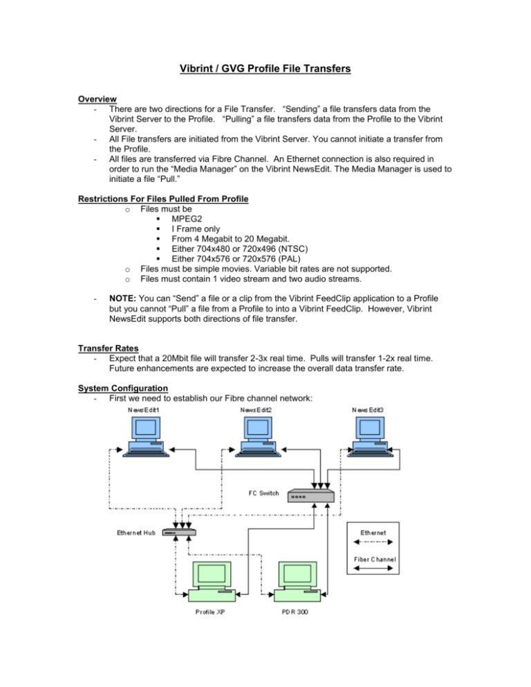
Vibrint / GVG Profile File Transfers Overview - There are two directions for a File Transfer. “Sending” a file transfers data from the Vibrint Server to the Profile. “Pulling” a file transfers data from the Profile to the Vibrint Server. - All File transfers are initiated from the Vibrint Server. You cannot initiate a transfer from the Profile. - All files are transferred via Fibre Channel. An Ethernet connection is also required in order to run the “Media Manager” on the Vibrint NewsEdit. The Media Manager is used to initiate a file “Pull.” Restrictions For Files Pulled From Profile o Files must be MPEG2 I Frame only From 4 Megabit to 20 Megabit. Either 704x480 or 720x496 (NTSC) Either 704x576 or 720x576 (PAL) o Files must be simple movies. Variable bit rates are not supported. o Files must contain 1 video stream and two audio streams. - NOTE: You can “Send” a file or a clip from the Vibrint FeedClip application to a Profile but you cannot “Pull” a file from a Profile to into a Vibrint FeedClip. However, Vibrint NewsEdit supports both directions of file transfer. Transfer Rates - Expect that a 20Mbit file will transfer 2-3x real time. Pulls will transfer 1-2x real time. Future enhancements are expected to increase the overall data transfer rate. System Configuration - First we need to establish our Fibre channel network: Setup Steps: 1.) Establish a Fibre Channel Connection a. If connecting point to point, simply connect the FC cable between the Vibrint FC interface card and the Profile’s FC interface card. i. NOTE: When connecting point to point, it is essential that the optical FC cable be crossed when plugged in between the two systems. b. If connecting multiple systems, connect all FC cables to the Fibre channel switch i. Multiple systems require the addition of a Fibre Channel switch - Usually a Brocade Silkworm 2800 Fibre Channel switch. c. Most systems (both Profile and Vibrint) will use the Interphase 5526 FC interface card. This is an optical card. 2.) Establish an Ethernet Connection a. Set up an Ethernet connection between all of the computers in the network using CAT-5 Ethernet cable. b. Multiple systems will require the addition of an Ethernet hub or switch. 3.) Set the FC interfaces’ MTUSize on Each NewsEdit a. The Fibre Channel interface card’s MTU size must be set to 32768 for maximum performance. For Vibrint software versions prior to 2.0, this must be done manually. To do this, perform the following steps: i. From the Start Menu, select Run… ii. Run “REGEDIT” iii. Set HKEY_LOCAL_MACHINE\SYSTEM\ControlSet001\Services\ix526i\Para meters\Mtusize to 0x8000 or 32768 decimal. 4.) Establish IP Addresses a. IP addresses must be established for both the Fibre Channel and the Ethernet connections for both the Vibrint Servers and Profiles. Make sure that the IP addresses chosen for a given interface share the same prefix. That is, FC IP address for both the Profiles and Vibrint Servers must share the first 9 digits. Similarly, the Ethernet IP address for both the Profiles and Vibrint Servers must share the first 9 digits. i. For the Profile 1. The Fibre Channel address can be set by using the “Configuration Manager”. ii. For Vibrint: 1. Select the Network Control Panel. 2. Select the Protocols tab 3. Select TCP/IP Protocol 4. Click on the Properties button. 5. Using the pull down, select the appropriate interface card (Ethernet or FC) 6. Select the Specify IP Address button 7. Enter your IP address in the space provided 8. Click on the subnet mask area to automatically generate a subnet mask. 9. Click OK 5.) Set Bindings i. For each Vibrint perform the following steps: 1. On the desktop of each computer, right mouse click on Network Neighborhood and select Properties. 2. Click on the “Bindings” tab 3. Using the pull down list, select “All Services” 4. Click on all + signs to expand all lists to their fullest extents 5. For each item shown, there should be two (2) network card descriptions. One of these is your Ethernet card, the other your Fibre channel card. For each heading, click on one of the two cards and by using the Move Up and Move Down buttons, make sure the Fibre Channel card appears first in each list. 6. Using the pull down list, select “All Protocols” 7. Repeat steps 4 and 5 for the “All Protocols” selection. 8. Using the pull down list, select “All Adapters” 9. Repeat steps 4 and 5 for the “All Adapters” selection. 10. Click the OK button 6.) Reboot all systems. a. After performing steps 1 - 5, make sure to reboot the computers - starting with the Profiles. Once the Profiles have completed their reboots, reboot the Vibrint Servers. 7.) Add FC IP addresses to the host file of each Vibrint by: a. Launch the Notepad application and open file named: %SystemRoot%\system32\drivers\etc\hosts, usually set up as: C:\WINNT\system32\drivers\hosts. b. Type in the Fibre Channel IP address of each Profile in the network. Next to each address type in the name of the Profile and append the characters “_fc0” to each name. (For Vibrint software versions prior to 2.0, append the characters “_fc”). i. Example: 150.234.187.1 Gv006906_fc0 150.234.187.2 Gv006907_fc0 This allows the Vibrint Server to associate a FC IP address to a Profile’s network name. 8.) Place all Profiles and Vibrint Servers on the same workgroup. a. For each Vibrint Server: i. Select the Network Control Panel. ii. Select the Identification tab iii. Click the Change… button iv. Click the Workgroup button v. Enter the name of the workgroup – NOTE: all computers must have the same name. vi. Click OK b. For each Profile: i. Testing Your Configuration: 1.) On each Profile run “fcping” from the command line or use the test utility in the Configuration Manager to ping all Fibre channel connections on the network. 2.) Run ping from the command line and ping all Ethernet connections. 3.) Repeat steps 1 and 2 from the Vibrint Servers. This can be easily done from a DOS prompt using the “ping” command. 4.) Launch Media Manager on all computers. Make sure that each Vibrint Server can see all Profiles. 5.) Launch NT Explorer on each Vibrint Server. Make sure that each Vibrint Server can see all other computers on the Ethernet. Initiating a Transfer 1.) On each Profile make sure the Port Server application is active. 2.) To initiate a “Send” from NewsEdit, you must first create a “Send Location”. Selecting the “Send” property page under the “Tools\Options” menu item can do this. i. Click the “Add” button. This will launch the “Add Named Destination to Send List” dialog. ii. Type in a “Send Name”. iii. Select “Profile” from the “Send Type” combo box. iv. Click “Browse” to find the Profile on the network or type in the computer name. v. Fill in the “User Name” (“movie”) and “Password” (i.e. usually a blank field) fields as needed. vi. Click “OK” to exit the “Add Named Destination to Send List”. vii. Click “OK” to leave the Property page. viii. Select a Sequence or a clip in the Bin and hit “F2”. This will launch the “Send List” dialog. This dialog contains your entire list of “Send Items”. By clicking on a “Send Item” you can view information about the “Send Location”. ix. Check the box next to each location that you want to send file to. You can select multiple locations and broadcast the file on a single send. The file will go to the top “Send Location” first and so on down the list. 1.) To initiate a “Pull” from a Profile into NewsEdit i. Launch the “Media Manager” application that has been loaded onto the Vibrint Server running NewsEdit. ii. Using “Media Manager,” establish a connection with the Profile. iii. Select the desired file and Drag and Drop it into a NewsEdit bin. ISSUES TO WATCH FOR: - For the PDR-300: o For networks that include a Fibre Channel switch, make sure that the “Enable Switch” mode is selected on the PDR-300. For networks that do not include Fibre Channel switches, you must disable the “Enable switch” option on the PDR-300. This can be done via the “Configuration Manager” under Fibre Channel Networks. o When connecting a NewsEdit and a PDR-300 point to point, you must make sure that the FC-switch microcode is loaded. After loading the microcode, go and deselect the “Enable Switch” mode option. This option gets enabled after loading the microcode. o You will need an MIA when connecting to a PDR-300: This will allow you to connect a Fibre optic cable to the copper connector that is on the PDR-300 FC interface card. - If you are getting an “Assert” (program crash) when transferring a file: o The host file may not be edited properly or not at all. o Audio files on a clip being transferred may be of different sizes or empty. - Network connection not found when trying to transfer. o The Profile needs to be rebooted - Extremely slow Pulls – Server Timeouts. o If you detect the pull to be extremely slow, 2x slower than real time or are experiencing error messages due to Server timeouts, this is may be because the Vibrint’s MTUSize has not been set properly.


