Heat Transfer II – Laboratory
advertisement
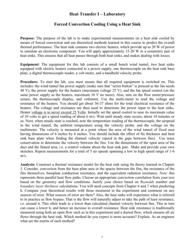
Heat Transfer I – Laboratory Forced Convection Cooling Using a Heat Sink Purpose: The purpose of the lab is to make experimental measurements on a heat sink cooled by means of forced convection and use theoretical methods learned in this course to predict the overall thermal performance. The heat sink contains two electric heaters, which provide up to 20 W of power to simulate an electronic component. You will apply approximately 15-20 W to a symmetric pair of heat sinks. This ensures that all heat passes through both heat sinks, and makes dealing with losses. Equipment: The equipment for this lab consists of a small bench wind tunnel, two heat sinks equipped with electric heaters connected to a power supply, one thermocouple on the heat sink base plate, a digital thermocouple reader, a volt meter, and a handheld velocity probe. Procedure: To start the lab, you must ensure that all required equipment is switched on. This includes: the wind tunnel fan power supply (make sure that “series button” is pressed as the fan needs 48 V), the power supply for the heaters (maximum voltage 25 V), and the fan speed control (on the same power supply as the heaters, maximum 10 V no more). Also, turn on the flow meter/pressure sensor, the thermocouple display, and voltmeter. Use the multi-meter to read the voltage and resistance of the heaters. You should get about 36-37 ohms for the total electrical resistance of the heaters. The voltage and resistance are then used to determine the power input to the heat sinks. Heater voltage is to never exceed 25 Volts. Initially set the speed control to near its maximum value of 10 volts to get a speed reading of about 6 m/s. Wait until steady state occurs, about 10 minutes or so. Next, when steady state is reached, note the temperature reading of the thermocouple, the airspeed in the wind tunnel, the ambient temperature using the velocity probe, and the voltage on the multimeter. The velocity is measured at a point where the area of the wind tunnel of fixed area having dimensions of 6 inches by 6 inches. You should include the effect of fin thickness and heat sink base plate when finding the channel velocity (speed in the gaps between fins). Use mass conservation to determine the velocity between the fins. Use the dimensions of the open area of the duct and the finned area, i.e. a control volume about the heat sink pair. Make and provide your own sketches. Repeat measurements for a total of 5 air speeds spanning a low to high speed range of 1-6 m/s. Analysis: Construct a thermal resistance model for the heat sink using fin theory learned in Chapter 3. Consider, convection from the base plate area in the spaces between the fins, the resistance of the fins themselves, baseplate conduction resistance, and the equivalent radiation resistance. Note: this represents three parallel heat flow paths. Choose an appropriate convection correlation from your text based on the geometry and flow conditions. Justify your choice based on Reynolds number and boundary layer thickness calculations. You will need concepts from Chapter 6 and 7 when predicting h. Compare your theoretical results with those measured in the experiment and comment on any sources of error. What sources of error are there? Also, the heat sinks will experience what is referred to in practice as flow bypass. That is the flow will naturally adjust to take the path of least resistance, i.e. around it. This often leads to a lower than calculated channel velocity between fins. This in turn can cause a lower h, and hence an increase in overall resistance. Heat sink resistance is traditionally measured using both an open flow such as in this experiment and a ducted flow, which ensures all air flows through the heat sink. Which method do you expect is more accurate? Explain. As an engineer what are the merits of each method? 1 The heat transfer coefficient will likely be predicted using the correlation for a flat plate from Chapter 7. The model assuming laminar flow is: NuL hL 0.664 Re L Pr1/ 3 k fluid Is the flow fully laminar for U = 1 – 6 m/s. The Reynolds number ReL must be less than 500,000. You must also check the boundary layer thickness between the fins to see if there will be interaction. Use criteria from Chapter 7 of your text to guide you. Note there are two characteristic flow lengths in this application. The fins have one length (9 mm) and the continuous surface between fins on the base has another (59.2 mm). Calculate h for each surface using the appropriate length scale in Re, and determine the resistance for the unfinned and finned surfaces. The dimensions of the heat sink are given below. In your analysis answer the following questions: a) Is radiation significant? Use the radiation heat transfer coefficient as an indicator. The heat sinks have an emissivity for anodized aluminum. Look up the emissivity in your text. Also for purposes of calculating the radiation heat transfer coefficient you will need a “representative” average surface temperature, as the heat sink will not be at the base temperature. Use the fin theory to guide you in finding a mean temperature for the heat sink that gives the same heat transfer rate if it were isothermal. b) Determine the effective resistance for one heat sink under measured conditions, i.e. Rtotal=( Ts - Tinfinity)/Qsink. Plot this as a function of free stream speed. c) Develop a theoretical thermal resistance curve for the heat sink for the range of your experimental data. d) Estimate the actual local velocity in the region of the fins by attempting to match the theory with measurements. How much flow actually passes through the heat sink? Calculate as a percentage. Note you should have less flow through the heat sink as it is not a ducted flow and hence < 100%. Dimensions of one heat sink: Fin Length (in flow direction) L = 9 mm Fin Height H = 21.2 mm Base Plate Width and Length W = 59.2 mm Fin Thickness (max) tf = 1.0 mm Baseplate Thickness tb = 3.1 mm Fin Spacing b = 2.0 mm Fin Count N = 105 Fins Thermal Conductivity k = 185 W/mK (Approximate Thermal Conductivity of the Aluminum Alloy) The fins are elliptic in cross-section. The area of an ellipse is Pi*(a*b) where a and b are the minor and major semi-axes. In this case b ~ 0.5 mm and a ~ 4.5 mm, i.e. half of the maximum thickness and length. You may model the fins as rectangular plates with uniform thickness of 0.785 mm. This gives 2 the same cross-sectional area as the elliptic shape, approximately! Base the perimeter on this shape, i.e. 0.785 mm x 9 mm. Use maximum fin thickness when you make an approximate flow balance to get the speed of the air between the fins. Lab Write Up Your lab write up will use a standard research paper format with two column formatting. Use the word template provided to you below. Your lab report should not exceed 8 pages in this format. That is typically the page limit that engineers and scientists abide by for technical conferences where such analysis and data are frequently reported. It will also facilitate grading for us, as we will be able to compare lab reports more easily. It will also save paper, which is good for the environment. This will give a good introduction to technical paper writing and presentation. It’s a useful skill to have when you start working, continue in graduate school, or just for the sake of doing something different! Note: if you do this lab correctly, you should get data that agree within 15-30% depending on the air speed. The error will be greater at low speeds as you are not accounting for mixed convection effects. See Chapter 9 for more on this. Also don’t forget that you have two heat sinks in parallel! 3 ENGR 6901 – Heat Transfer I Fall, 2011 Forced Convection Cooling of a Slotted Fin Heat Sink Group Member Names Faculty of Engineering and Applied Science Memorial University of Newfoundland St. John’s, NL, Canada, A1B 3X5 ABSTRACT Summarize what you did and what the key results/conclusions were in less than 300 words. RESULTS Summarize the data you collected and any other pertinent information. Keywords: Put the keywords here!1 ANALYSIS Provide details of the mathematical model you constructed to predict the heat transfer rate. Make comparisons of your measurements and predictions in graphical and tabular form. Be sure to clearly explain your reasons for using certain equations. NOMENCLATURE Summarize your nomenclature for all equation variables used in the analysis section. [Delete this text afterwards] A = Area (m2) Greek Symbols Φ = Distance to the Interface DISCUSSION Discuss your measurements and model predictions and consider sources of error to explain disagreements! Subscripts L = Liquid INTRODUCTION Explain in your own words what you are setting out to do, why you are doing it, and what you hope to learn. PROCEDURE Explain what you did in your own words. Don’t cut and paste what I wrote! EXPERIMENTAL FACILITY Explain the system in your own words. Don’t cut and paste my description! Include a schematic or image, etc. SUMMARY AND CONCLUSIONS Put a concise summary of accomplished! what was ACKNOWLEDGMENTS Put the acknowledgments here! Thank all those people that made this work possible, i.e. those who helped you. REFERENCES Put all your references in the format below. [Delete this text afterwords] [1] e-mail: your_email@mun.ca 4 Incropera, DeWitt, Bergman, Lavine, “Fundamentals of Heat and Mass Transfer”, 6th edition, John Wiley & Sons, 2007 5

