the johnson company patents, 1883-1895
advertisement
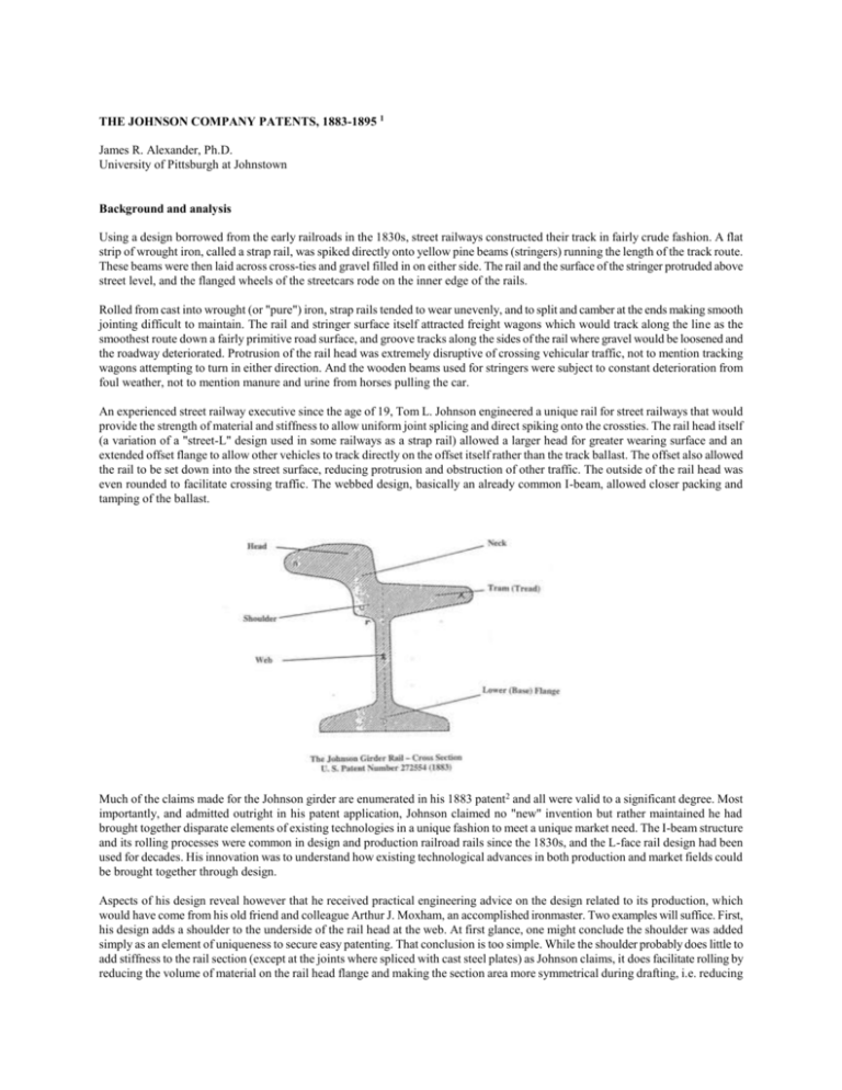
THE JOHNSON COMPANY PATENTS, 1883-1895 1 James R. Alexander, Ph.D. University of Pittsburgh at Johnstown Background and analysis Using a design borrowed from the early railroads in the 1830s, street railways constructed their track in fairly crude fashion. A flat strip of wrought iron, called a strap rail, was spiked directly onto yellow pine beams (stringers) running the length of the track route. These beams were then laid across cross-ties and gravel filled in on either side. The rail and the surface of the stringer protruded above street level, and the flanged wheels of the streetcars rode on the inner edge of the rails. Rolled from cast into wrought (or "pure") iron, strap rails tended to wear unevenly, and to split and camber at the ends making smooth jointing difficult to maintain. The rail and stringer surface itself attracted freight wagons which would track along the line as the smoothest route down a fairly primitive road surface, and groove tracks along the sides of the rail where gravel would be loosened and the roadway deteriorated. Protrusion of the rail head was extremely disruptive of crossing vehicular traffic, not to mention tracking wagons attempting to turn in either direction. And the wooden beams used for stringers were subject to constant deterioration from foul weather, not to mention manure and urine from horses pulling the car. An experienced street railway executive since the age of 19, Tom L. Johnson engineered a unique rail for street railways that would provide the strength of material and stiffness to allow uniform joint splicing and direct spiking onto the crossties. The rail head itself (a variation of a "street-L" design used in some railways as a strap rail) allowed a larger head for greater wearing surface and an extended offset flange to allow other vehicles to track directly on the offset itself rather than the track ballast. The offset also allowed the rail to be set down into the street surface, reducing protrusion and obstruction of other traffic. The outside of the rail head was even rounded to facilitate crossing traffic. The webbed design, basically an already common I-beam, allowed closer packing and tamping of the ballast. Much of the claims made for the Johnson girder are enumerated in his 1883 patent2 and all were valid to a significant degree. Most importantly, and admitted outright in his patent application, Johnson claimed no "new" invention but rather maintained he had brought together disparate elements of existing technologies in a unique fashion to meet a unique market need. The I-beam structure and its rolling processes were common in design and production railroad rails since the 1830s, and the L-face rail design had been used for decades. His innovation was to understand how existing technological advances in both production and market fields could be brought together through design. Aspects of his design reveal however that he received practical engineering advice on the design related to its production, which would have come from his old friend and colleague Arthur J. Moxham, an accomplished ironmaster. Two examples will suffice. First, his design adds a shoulder to the underside of the rail head at the web. At first glance, one might conclude the shoulder was added simply as an element of uniqueness to secure easy patenting. That conclusion is too simple. While the shoulder probably does little to add stiffness to the rail section (except at the joints where spliced with cast steel plates) as Johnson claims, it does facilitate rolling by reducing the volume of material on the rail head flange and making the section area more symmetrical during drafting, i.e. reducing the extrusion effect during hot rolling that would cause the rail to camber. At the same time, the shoulder allows the producer to design uniform splice plates for both sides of the web, avoiding the need to design an intricate fit of inside and outside splice plates. Secondly, the vertical location of the rail head itself over the web appears a compromise of several considerations. To prevent flexing (or "wobbling") of the rail head and thereby promoting longer structural life, the rail head ought to be directly over the web. Yet the rail head is offset, opening the possibility of minor counterclockwise flexing and structural cracks at the web. But understanding the multiple uses of the rail in city streets most assuredly lead Johnson to extend the inside flange for use of other vehicular traffic, which itself would cause minor clockwise flexing and reduce the average tendency of the rail section to crack at the web. Finally, the offset, to the degree that flexing in either direction did occur, would in fact cause a minor tamping effect on roadway ballast around the rail. In short, while Johnson's rail section design was an application of existing technologies, it was an application to a unique market problem which only Johnson, an experienced street railway manager, would understand. Just as clearly, the design had been altered to accommodate peculiar production considerations, specifically those of drafting wide, offset flanges and a shoulder. It may well be that Johnson realized some of these advantages after the design was successfully rolled, and his claims simply incorporated some of them. Nevertheless, the design proves to be an innovative application of existing technology, expertly adapted to the discipline of existing production technologies. Bringing the Johnson girder design to successful production was a fairly intricate task. While flat rolling of I-beam structures from iron was common for railroad rails by the 1870s, the standard railroad T-rail head design was a far heavier rail, and possessed neither the offset in surface flanges nor the width exhibited in the offset (inside) flange designed for tracking of other street vehicles. The Johnson rail was a much lighter rail (designed at approximately 32 pounds as opposed to 100-120 pounds for railroad T-rails) and required unique (and uncommon for the time) drafting design and sequencing. After two years of perfecting the roll design for the Johnson rail in Louisville, Moxham recognized the rail could not be rolled of wrought iron, and his Louisville plant did not have the capacity to roll it from steel. In order to focus his attention on track work design and fabrication, Moxham contracted with Daniel Morrell of the Cambria Iron Company to roll the rails from steel. Cambria Iron had rolled a more primitive girder rail design with offset for the cable road in San Francisco in 1877, but had not pursued the street railway market because of its small market size. Electrification of street railways was still some ten years off. Wrought iron was the standard rolling material for the early railroads and horse-drawn street railways. Cambria Iron had pioneered commercial production of steel T-rails for railroads in 1871. But by 1880, street (strap) rails were still rolled from iron, primarily because of the higher cost of steel. Furthermore, because of the lightness of street rail, wear strength was less a problem than cambering and wear unevenness. Track was repaired when the ride was so jarring that ridership declined rather than when rails simply wore out. The principal difficulty with the standard street rail then was not its durability but its spiking and jointing. The Johnson design addressed those two problems admirably, but its offset design guaranteed it could not be rolled from wrought iron. Wrought iron, the material used in strap rails, is essentially a carbon free, laminated composite of layers of pure iron and slag. Produced primarily by puddling techniques, wrought iron is never reduced to a liquid state and therefore never homogenizes itself, leaving layers of oxides in the metal. While the grain structure (porosity) of the resulting metal can be flattened and elongated by forging, and perhaps increasing the metal's strength and ductility, irregularities in the metal remain, exposed during wear. These oxides could be eliminated in the process of making steel prior to adding back the appropriate carbon content. Wrought iron remained a viable metal for both T-rails and strap rails because the rolling action exposed the metal to longitudinal stress, essentially compressing and forming the metal along the same line as its grain structure. As Moxham discovered in his rolling experimentation in Louisville, the drafting of Johnson's widened and offset flanges subjected the metal to transverse stress, essentially drafting it across its grain structure, causing cobbling. The metal tended to crack and splinter before it would completely fill out the flanges. This was not common knowledge at the time, for even by the mid-1880s, most ironmasters (virtually all steelmakers and fabricators started as iron rolling mills) considered iron, with its reduced carbon content to be more ductile (less brittle) than steel. The experienced ironmaster like Moxham would have discovered however that during hot rolling, wrought iron could be less workable that steel for reasons not related to either its properties at room temperature or its cleanliness. While wrought iron could prove to be more ductile when stressed in a longitudinal direction; it proved to be less ductile when stressed in a transverse direction. Moxham had learned, and accommodated into his production processes, a lesson concerning the properties of iron that could only become known through experience: that for a given temperature or level of cleanliness, some steels have greater inherent ductility that low carbon (wrought) iron. This would allow such steels to be rolled into more complex shapes, largely requiring application of transverse stress (drafting) in flat or diagonal rolling. For those shapes that are possible for both steel and low carbon iron, such steels may be easier to roll into a specific shape than iron. It is instructive that Moxham designed his roll processes to the Johnson rail section template based on his experience in rolling wrought iron, and even though the material used was changed to steel when ultimately (and successfully) rolled by Cambria Iron, the integrity of his roll design stood up. He was a roll engineer by apprenticeship and practical experience, the common and traditional method of learning the craft in the latter half of the 19th century, and adapted his designs and sequence over a period of three years by practical intuition. One can certainly not argue that Moxham's roll design was radically different than common practice of the day. I-beam structures had been rolled for over forty years before Moxham attempted the Johnson rail section. Certainly some complex shapes requiring drafting (transverse stress) were not uncommon among rolling mills, and at least one of the early steel mills (Cambria Iron) had experimented somewhat with offset rail heads. But apparently no rolling mill prior to 1883, except for Louisville Iron and Steel Company in the 1880-1882 period, had been set up specifically to roll this type of offset rail section from either iron or steel. The resulting roll design and sequence patented in 18843 is in most respects consistent with modern rolling practices. In the initial patented sequence, the roughing sequence (passes one through six) is designed to heal porosity, refine the grain structure and prepare the form for the finishing sequence. The first five passes alternate between working (compressing or dummy) passes and forming (or edge) passes, though it is doubtful the rail came through passes two and four with the degree of straightness claimed in the patent application. The sixth pass is the major forming pass.4 In the finishing set (warm-working passes seven through eleven), little drafting is accomplished and it is possible that with greater reduction at pass seven, the sequence could be accomplished in two or three fewer passes. Such a conclusion however lacks Moxham's experience and eye - to produce the designed cross section and a straight rail using the steel blooms at that level of technology, eleven passes may have been required. Other questions arise from a closer scrutiny of Moxham's original patent description and drawings, questions that would arise only because the inevitable advance of time, experience and technical knowledge. The modern day roll engineer would have doubts about whether, without bevels on the sides of passes, such deep passes wouldn't cause cobbling in the finishing set or whether a 16-inch diameter roll wouldn't be too small to withstand the firecracking in the roughing stand. In fact, when Moxham built his own rolling mill in 1888, he used 26-inch rolls. Doubts would indeed be raised concerning Moxham's claim of an increased cross-sectional area after the fifth roughing pass.5 In summary, it is clear that both Johnson and Moxham were accomplished technicians in their fields, based on practical experience and innovative market and production sense. In their patents, neither man created new knowledge in his field and neither man claimed to. Rather, they had successfully brought together state-of-the-art technical knowledge from separate (marketing and production) fields into a product that met a peculiar market need.6 The question of its production presented a series of complex problems (regarding material, structure and roll design) that could be overcome only with relevant experience of the ironmaster on the floor (remembering that little industrial laboratory capacity had developed in the steel industry by this time), perseverance (even at Cambria Iron the successful roll of the Johnson section was accomplished after five months of experimentation), and significant financial backing. This conclusion is supported as well by the legal history of the Johnson and Moxham patents, the latter of which were successfully challenged in the early 1890s as not representing true "invention" i.e. new knowledge, but rather representing a common application of contemporary knowledge. It could be argued that Johnson (whose patent was never challenged but could have been without difficulty) simply adapted a common railroad I-beam structure by changing its head to an L-face design to accommodate street railways. Similarly, it could be argued that Moxham simply adapted standard rolling practices to accommodate the peculiarities of Johnson's design. Neither, it could be argued, was particularly innovative; both were simply competent craftsmen. Such a conclusion would be far too simple. It belies the sophistication of the 'craftsmanship' exhibited in the Johnson application and the Moxham adaptation, particularly if one considers the time and the state of technical knowledge. Innovation in fact took place. Johnson saw the application because he was familiar with disparate pieces of technical knowledge and he had access to (and could communicate with) Moxham who in turn could anticipate production problems. For his part, Moxham's experience on the roll floor and his intuitive sense for mechanical properties of iron at certain temperatures contributed to his innovative adaptation of roll technology to the offset design and his intuitive abandonment of wrought iron in favor of bessemer steel. List of the Patents7 The following is a listing of all the patents secured by Arthur J. Moxham, Tom L. Johnson, the Johnson Steel Street Rail Company (the Johnson Company after 1888) and individuals who consigned their patent rights to the Company for rail section design (sideflanged or center-bearing, girder, guard, or groove rails), track work design (such as curves, crossings, switches and frogs), track work peripherals (such as chairs, clips, cross-ties, and splice-plates), roll and roll mill design, tool design (such as dies and chucks), and track construction machinery (notably electric welding processes). Most of these patents cover products or manufacturing processes related specifically to either horse-drawn railway systems or (after 1888) electrified railway systems. Included in each citation are the U.S. Patent Office Number, the name of the person to whom it was issued, and a brief description of the product or process patented. For some of the most important earlier patents, the date of issue (and sometimes the date and place of application) is cited in parentheses. Patents issued to an individual or individuals under the Johnson Steel Street Rail Co. (*) or the Johnson Company (**) are noted by asterisks. 1883 (3) 272554 Johnson, T. 276419 Johnson 289355 Moxham, A. J.* J-bird railhead design (filed Sept.11, 1882 Indianapolis, issued Feb. 20) Street railway curve and frogs (filed Oct. 31, 1882 Indianapolis, issued Apr. 24) Street rail and splice design (filed July 25, 1883 Louisville, issued Nov. 27) 1884 (3) 292655 Johnson, Tom Double-flanged T-rail head design (filed Feb. 20, 1883 Indianapolis, issued Jan. 29) 292759 Moxham/Tranter,J. J-bird roll design (filed Nov. 23, 1882 Louisville, issued Jan. 29) 303036 Moxham J-bird design rolling mill (filed Nov. 26, 1883 Louisville, issued Aug. 5) 1885 (19) 310457 312213 313512 316994 316995 317665 318645 319009 319010 319011 321627 330997 330998 331525 331526 333474 333475 331012 331013 Moxham Moxham Moxham Moxham Moxham Moxham Moxham Moxham Moxham Moxham Moxham Moxham Moxham Moxham Moxham Moxham Moxham Townsend, J.* Townsend* Making steel girder rails (issued Jan. 6) J-bird rolling mill design (filed Aug. 16, 1884 Johnstown, issued Feb.10) Securing girder rails in track (issued Mar. 10) Girder rail and rail joint (issued May 5) Metal chair for street railways (issued May 5) Built-up girder rail (issued May 12) Street railway switch (issued May 26) T-rail roll design (filed Mar. 8, 1884 Louisville, issued June 2) Metal cross-tie for railways (issued June 2) Street railway frog (issued June 2) J-bird roll design (issued July 7) J-bird three-high roll design (issued Nov. 24) J-bird roll design (issued Nov. 24) Street railway switch (issued Dec. 1) Street railway switch (issued Dec. 1) Street railway switch (issued Dec. 29) J-bird roll design (issued Dec. 29) Street railway chair design Street railway frog design 1886 (5) 334265 Moxham 338181 Moxham Splice bar rail chair: all types Street railway frog 340891 Moxham 344396 Moxham 350549 Moxham Girder rail roll design Girder rail roll design Street railway frog 1887 (26) 355777 355778 355779 355780 355781 355782 357849 358122 358619 360036 360780 364725 366497 366498 366598 367433 367434 367654 367655 374265 364996 367746 368142 362455 357532 366507 Moxham Moxham Moxham Moxham Moxham Moxham Moxham Moxham Moxham Moxham Moxham Moxham Moxham Moxham Moxham Moxham Moxham Moxham Moxham Moxham Entwisle, E.B.* Entwisle* Entwisle* Marshall, C.A.* Meysenburg, O.* Richards, C.A.* Roll design Metallic core post for tracks Street railway chair Center-bearing girder rail roll process Center-bearing type roll design Center-bearing type rail splice joint Street railway chair Street rail chair spike design Street railway frog Roll design Paving block for railway beds Tongue switch for street railways Curved crossing design T-chair design Movable tongue switch Crossing design Street railway chair Pocket-filling device for girder rails Combination crossing & switch Railway crossing design Railway chair design Railway crossing design Die for railway chairs design Railway gip and key Cast iron brace chair design Grooved girder rail design 1888 (24) 378209 378210 378211 383001 383002 383003 391549 391550 391552 391553 394078 394079 395248 395249 387147 381875 387170 394122 394021 394022 394023 394024 391565 388097 Moxham Moxham Moxham Moxham Moxham Moxham Moxham Moxham Moxham Moxham Moxham Moxham Moxham Moxham Colley, F.* Entwisle* Lloyd, C. F.* Lloyd * Simpson, E.* Simpson* Simpson* Simpson* Street, C. F.* Welch, R. W.* 1889 (12) Roll design Roll design Center-bearing flangeless roll design Grooved girder rail Double-grooved girder rail Acute curve crossing design Rail and rail joint design Rolling machine Two-part girder rail Rail and rail chair design Brace chair Rail chair design Expansion joint for track Portable passing switch Rolls, overhanging slot rails Die for making railway chairs Flexible guide for rolling mills Rolling mill design Mill, side-flanged guard rails Mill, side-flanged groove rails Mill, side-webbed girder rails Mill, side-flanged center-bear rail Switch joint chair for railways Rail chair for girder rails 402470 408843 408844 413956 401691 401692 401963 410821 410955 414153 409114 409131 Moxham Moxham Moxham Moxham Colley** Colley** Colley** Colley ** Colley ** Goughnour, H.** O'Connell, P.** Wettergreen, J.** Railway crossing Rolling steel or iron Rolling steel or iron Adjustable clamp Roll design Roll design Roll design Machine for rolling Roll design Two-part railway chair Interlocking brace chair Railway brace chair 1890 (12) 423072 427348 427349 435704 436987 436988 442165 435680 442175 418986 436959 436960 Moxham Moxham Moxham Moxham Moxham Moxham Berriman, R.** Brown, W. M.** Entwisle** Reilly, F. P.** Suppes, M.** Suppes** Railway chair Railway rail and chair Rolling mill Securing girder rail to track Railway chair Railway chair Double brace chair Railway chair Box chair for girder rails Railway chair Railway brace chair Roll pass Entwisle** Suppes** Suppes ** Suppes** Railway crossing Railway rail Railway rail Making rails 1891 (4) 447130 460063 460064 460096 1892 (30) 472767 477672 477673 477674 477675 477676 477677 477678 477679 477680 477681 477682 477683 477684 477685 477686 477687 477688 477689 477690 483801 482802 482803 Moxham Moxham Moxham Moxham Moxham Moxham Moxham Moxham Moxham Moxham Moxham Moxham Moxham Moxham Moxham Moxham Moxham Moxham Moxham Moxham Moxham Moxham Moxham Box brace chair for girder rails Expansion rail for railways Rail for railways Rail for railways Expansion rail for railways Railway crossing Rail joint Railway rail joint Combined rail and cross tie Railway rail joint Railway crossing Railway crossing Rail for railways Frog or cross for railway crossings Railway crossing Switch-piece for railway tracks Railway crossing Railway crossing Railway rail joint Railway rail and making the same Railway chair Railway rail chair Channel-rail and chair 482804 482805 477641 486211 482092 478806 482807 Moxham Railway rail chair and making same Moxham Combined rail & chair Brown, W. M.** Railway brace chair Hunter, R. M.** Girder rail and manufacture8 Lavelle, P. J.** Chair manufacture and die Murray, G.** Railway brace chair Murray Railway brace chair 1893 [34] 492469 495985 495986 495987 495988 495989 496890 497808 498074 500929 500930 500931 505988 505989 505990 508036 508037 508038 492458 494243 508095 492885 492464 495967 505978 508012 498724 510047 504818 508049 489508 496017 496916 500973 Moxham Moxham Moxham Moxham Moxham Moxham Moxham Moxham Moxham Moxham Moxham Moxham Moxham Moxham Moxham Moxham Moxham Moxham Brown** Brown** Entwisle** Evans, E. O.** Evans, H. C.** Evans, H. C.** Ford, H. E.** Gull, J. M.** O'Shea, H.** Pfefferkorn, W.** Reilly, F. P.** Reilly** Suppes** Suppes** Suppes** Suppes** Tie rod for railway tracks Rail chair for railway rails Rail and support Railway track Rail joint Welding metal Welding metal Railway rail and uniting same Rail and chair, and uniting same Transfer table for railways Switch piece Railway chair Method of securing metal objects Railway rail support Railway rail joint Apparatus for welding Welding clamp Railway track Interlocking rail chair Railway brace chair Railway switch Joint box Railway rail and chair Railway rail and chair Joint and support Welding process Railway crossing Tie-plate Railway chair Rail support and cross-tie Railway brace chair Rack-rail Girder joint Electric welding machine 1894 [22] 513711 513712 518197 520654 520694 526455 530196 530197 531444 531445 531446 519298 526434 520359 Moxham Moxham Moxham Moxham Moxham Moxham Moxham Moxham Moxham Moxham Moxham Benagh, H. C.** Brown** Hunter** Railway joint Railway chair and cross-tie Machine for straightening rails/bars Making railway chairs Tongue switch Railway crossing Bending flanged metal bars Railway crossing Railway rail Electric connections Railway track Railway switch Joint metal bars Electric welding apparatus 520360 520860 520861 520862 530240 520090 517075 526466 Hunter** Electric welding apparatus O'Shea** Railway chair O'Shea** Railway frog O'Shea** Railway tongue switch Pfefferkorn** Machine for bending bars Suppes** Draw bar Suppes** Railway rail and chair Thomas, H.W.** Roll bearing for rolling mill 1895 [14] 533725 536734 536735 539878 540796 537601 546773 550045 533713 533714 533735 532817 544006 551649 Moxham Moxham Moxham Moxham Moxham Brown** Brown** Goughnour** Leighton, H.** Leighton** O'Shea** Raymond, W.** Raymond** Raymond** Pattern for switch work Pattern for switch work Pattern for switch work Pattern for switch work Pattern for switch work Railway switch Welding clamp Slack adjuster Straightening machine Straightening machine Switch work pattern Railway switch Chuck for machine tools Railway track construction end 1 Initially presented in James R. Alexander, The Johnson Steel Street Rail Company; Historic Documentation (Historic American Engineering Record/American’s Industrial Heritage Project 1988), appendices C and D. 2 U. S. Patent Number 272154. Street-Railroad Rail, Tom L. Johnson, Indianapolis, Indiana, filed September 11, 1882, issued February 20, 1883. 3 U. S. Patent Number 292759, Roll for Rolling Car-Rails, Arthur J. Moxham and John R. Tranter, Louisville, Kentucky, filed October 23, 1882, issued January 29, 1884. 4 An alternative sequence, patented that same year, U. S. Patent Number 303036, Rolling Mill, Arthur J. Moxham, Louisville Kentucky, filed November 26, 1883, issued August 5, 1884, prescribes an alternative four-pass roughing sequence that enters the bloom into the sequence on the diagonal. 5 The same is claimed for the fourth roughing pass in U. S. Patent Number 303036 (note 4 supra). 6 This is the argument presented in James R. Alexander, “Technical Innovation in Steel Fabrication: Marketing and Production Considerations in the Development of the Johnson Rail,” Business and Economic History, Second Series, Vol. 20 (1991): 210-215. 7 From the Annual Report of the Commissioner of Patents, during the period 1874-1895. Not included in the 204 patents listed here are the significant number of patents held by Johnson for specialized cable systems, such as yoke design, slot rails, crossings, and braking systems, patents for the design of car fare-boxes secured by Johnson: 132535 (1872) and 143698 (1873) and Moxham: 149671 (1874), and Moxham’s earlier patents on processes for strengthening iron: 192653 (1877), 193540 (1877) and 210049 (1878). 8 Hunter consigned most of his work out of Philadelphia for Thomson-Houston Electric, including 13 patented welding processes and electric designs in 1894. Johnson Company began laying track with continuous electric welding in 1892.
