Gear Train I - WordPress.com
advertisement
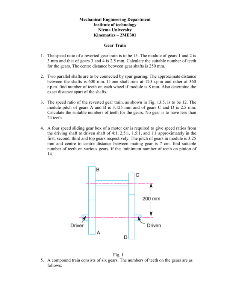
Mechanical Engineering Department Institute of technology Nirma University Kinematics – 2ME301 Gear Train 1. The speed ratio of a reverted gear train is to be 15. The module of gears 1 and 2 is 3 mm and that of gears 3 and 4 is 2.5 mm. Calculate the suitable number of teeth for the gears. The centre distance between gear shafts is 250 mm. 2. Two parallel shafts are to be connected by spur gearing. The approximate distance between the shafts is 600 mm. If one shaft runs at 120 r.p.m and other at 360 r.p.m. find number of teeth on each wheel if module is 8 mm. Also determine the exact distance apart of the shafts. 3. The speed ratio of the reverted gear train, as shown in Fig. 13.5, is to be 12. The module pitch of gears A and B is 3.125 mm and of gears C and D is 2.5 mm. Calculate the suitable numbers of teeth for the gears. No gear is to have less than 24 teeth. 4. A four speed sliding gear box of a motor car is required to give speed ratios from the driving shaft to driven shaft of 4:1, 2.5:1, 1.5:1, and 1:1 approximately in the first, second, third and top gears respectively. The pitch of gears in module is 3.25 mm and centre to centre distance between mating gear is 7 cm. find suitable number of teeth on various gears, if the minimum number of teeth on pinion of 14. Fig. 1 5. A compound train consists of six gears. The numbers of teeth on the gears are as follows: Gear: A B C D E F No. of teeth: 60 40 50 25 30 24 The gears B and C are on one shaft while the gears D and E are on another shaft. The gear A drives gear B, gear C drives gear D and gear E drives gear F. If the gear A transmits 1.5 kW at 100 r.p.m. and the gear train has an efficiency of 80 per cent, find the torque on gear F. 6. Two parallel shafts are to be connected by spur gearing. The approximate distance between the shafts is 600 mm. If one shaft runs at 120 r.p.m. and the other at 360 r.p.m., find the number of teeth on each wheel, if the module is 8 mm. Also determine the exact distance apart of shaft. 7. In an epicyclic gear train, an arm carries two gears A and B having 36 and 45 teeth respectively. If the arm rotates at 150 r.p.m. in the anticlockwise direction about the centre of the gear A which is fixed, determine the speed of gear B. If the gear A instead of being fixed makes 300 r.p.m. in the clockwise direction, what will be the speed of gear B?(Use Fig.2) 8. In an epicyclic gear train, the internal wheels A and B and compound wheels C and D rotate independently about axis O. The wheels E and F rotate on pins fixed to the arm G. E gears with A and C and F gears with B and D. All the wheels have the same module and the numbers of teeth are: TC = 28; TD = 26; TE = TF = 18. 1. Sketch the arrangement; 2. Find the number of teeth on A and B; 3. If the arm G makes 100 r.p.m. clockwise and A is fixed, find the speed of B; 4. If the arm G makes 100 r.p.m. clockwise and wheel A makes 10 r.p.m. counter clockwise; find the speed of wheel B. 9. In an epicyclic gear of the ‘sun and planet’ type shown in Fig. 3, the pitch circle diameter of the internally toothed ring is to be 224 mm and the module 4 mm. When the ring D is stationary, the spider A, which carries three planet wheels C of equal size, is to make one revolution in the same sense as the sun wheel B for every five revolutions of the driving spindle carrying the sun wheel B. Determine suitable numbers of teeth for all the wheels. Fig. 2 Fig.3 10. Fig. 4 shows an epicyclic gear train known as Ferguson’s paradox. Gear A is fixed to the frame and is, therefore, stationary. The arm B and gears C and D are free to rotate on the shaft S. Gears A, C and D have 100, 101 and 99 teeth respectively. The planet gear has 20 teeth. The pitch circle diameters of all are the same so that the planet gear P meshes with all of them. Determine the revolutions of gears C and D for one revolution of the arm B. 11. In the gear drive as shown in Fig. 13.18, the driving shaft A rotates at 300 r.p.m. in the clockwise direction, when seen from left hand. The shaft B is the driven shaft. The casing C is held stationary. The wheels E and H are keyed to the central vertical spindle and wheel F can rotate freely on this spindle. The wheels K and L are rigidly fixed to each other and rotate together freely on a pin fitted on the underside of F. The wheel L meshes with internal teeth on the casing C. The numbers of teeth on the different wheels are indicated within brackets in Fig. 13.18. Find the number of teeth on wheel C and the speed and direction of rotation of shaft B. Fig.4 Fig.5 12. In a gear train, as shown in Fig. 6, gear B is connected to the input shaft and gear F is connected to the output shaft. The arm A carrying the compound wheels D and E, turns freely on the output shaft. If the input speed is 1000 r.p.m. counter- clockwise when seen from the right, determine the speed of the output shaft under the following conditions: 1. When gear C is fixed and 2. When gear C is rotated at 10 r.p.m. counter clockwise. Fig.6


