Section #26 05 14 - Power Cable and Overhead Conductors (1000 V)
advertisement
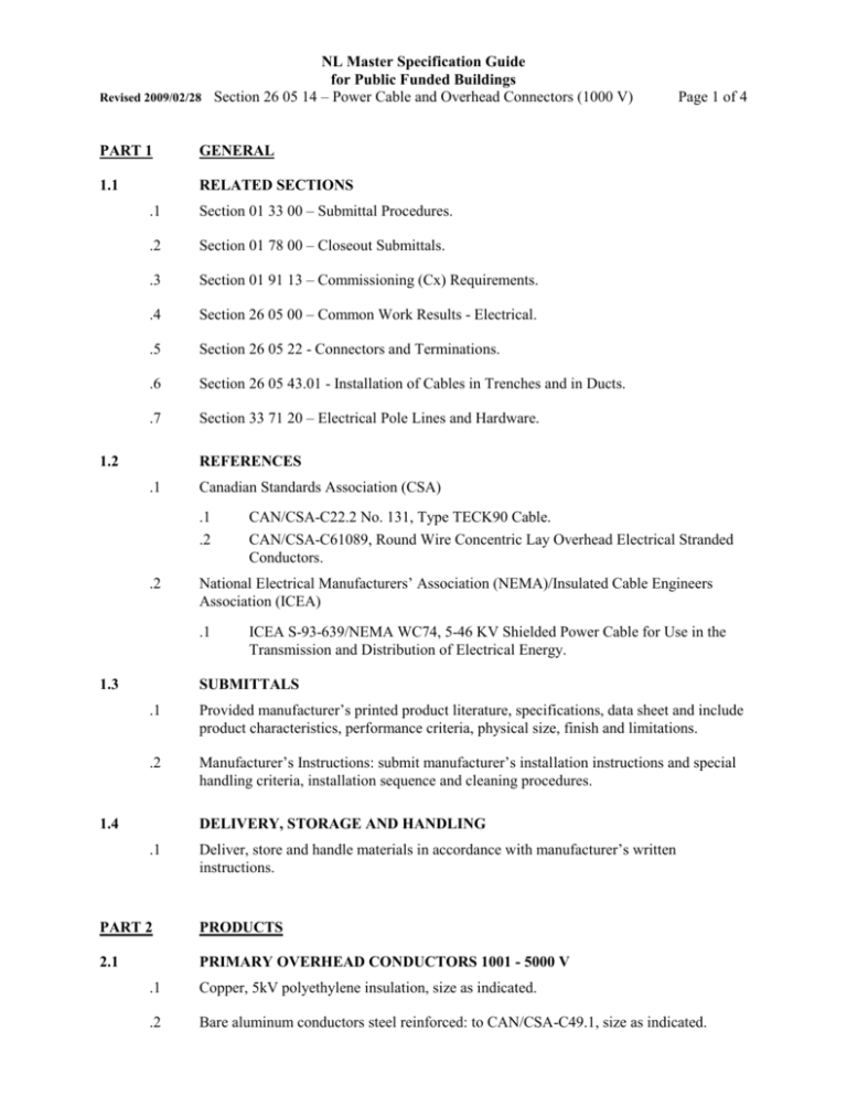
NL Master Specification Guide for Public Funded Buildings Revised 2009/02/28 Section 26 05 14 – Power Cable and Overhead Connectors (1000 V) PART 1 GENERAL 1.1 RELATED SECTIONS .1 Section 01 33 00 – Submittal Procedures. .2 Section 01 78 00 – Closeout Submittals. .3 Section 01 91 13 – Commissioning (Cx) Requirements. .4 Section 26 05 00 – Common Work Results - Electrical. .5 Section 26 05 22 - Connectors and Terminations. .6 Section 26 05 43.01 - Installation of Cables in Trenches and in Ducts. .7 Section 33 71 20 – Electrical Pole Lines and Hardware. 1.2 Page 1 of 4 REFERENCES .1 Canadian Standards Association (CSA) .1 .2 .2 National Electrical Manufacturers’ Association (NEMA)/Insulated Cable Engineers Association (ICEA) .1 1.3 CAN/CSA-C22.2 No. 131, Type TECK90 Cable. CAN/CSA-C61089, Round Wire Concentric Lay Overhead Electrical Stranded Conductors. ICEA S-93-639/NEMA WC74, 5-46 KV Shielded Power Cable for Use in the Transmission and Distribution of Electrical Energy. SUBMITTALS .1 Provided manufacturer’s printed product literature, specifications, data sheet and include product characteristics, performance criteria, physical size, finish and limitations. .2 Manufacturer’s Instructions: submit manufacturer’s installation instructions and special handling criteria, installation sequence and cleaning procedures. 1.4 DELIVERY, STORAGE AND HANDLING .1 Deliver, store and handle materials in accordance with manufacturer’s written instructions. PART 2 PRODUCTS 2.1 PRIMARY OVERHEAD CONDUCTORS 1001 - 5000 V .1 Copper, 5kV polyethylene insulation, size as indicated. .2 Bare aluminum conductors steel reinforced: to CAN/CSA-C49.1, size as indicated. NL Master Specification Guide for Public Funded Buildings Revised 2009/02/28 Section 26 05 14 – Power Cable and Overhead Connectors (1000 V) 2.2 RUBBER INSULATED CABLES 1001 - 5000 V Page 2 of 4 .1 Conductors: copper size as indicated. .2 Insulation: cross-linked polyethylene compound rated RWU90. .3 Insulation shielding: semi-conducting non-metallic tape over insulation, and served wire shield over tape. .4 Cable jacket: thermosetting with separator tape between shield and jacket. 2.3 ALUMINUM SHEATHED CABLES 1001 - 5000 V .1 Conductors: copper size as indicated. .1 Insulation: cross-linked polyethylene Type RA90 rated 5kV. .2 Sheath: seamless, corrugated, aluminum. .3 Outer covering: extruded PVC. 2.4 CONCENTRIC NEUTRAL POWER CABLE 1001 - 5000 V .1 Single copper conductor, size as indicated. .1 Semi-conducting strand shield. .2 Insulation: cross-linked polyethylene rated 90C and 5kV. .3 Semi-conducting insulation shielding layer. .4 Copper neutral wires applied helically over insulation shield equivalent to 100% full capacity. .5 Separator mylar tape over neutral wires. .6 Extruded PVC jacket rated minus 40C. 2.5 PRIMARY OVERHEAD CONDUCTORS 5001 - 15000 V .1 Bare, copper conductors, size as indicated. .2 Bare aluminum conductors steel reinforced: to CAN/CSA-C49.1, size as indicated. 2.6 RUBBER INSULATED CABLES 5001 - 15000 V .1 Single copper conductor, size as indicated. .2 Strand shielding. .3 Insulation: of chemically cross-linked thermosetting polyethylene material rated 90C and 15 kV to NEMA WC7-1992/ICEAS-66-524. .4 Insulation shielding of semi-conducting non-metallic tape over insulation, and served wire shield over tape. NL Master Specification Guide for Public Funded Buildings Revised 2009/02/28 Section 26 05 14 – Power Cable and Overhead Connectors (1000 V) .5 Barrier tape over shield. .6 2.7 Page 3 of 4 Overall jacket of PVC rated minus 40C. CONCENTRIC NEUTRAL POWER CABLES 5001 - 15000 V .1 Concentric neutral power cable: to NEMA WC7 ICEAS-66-524. .2 Single copper conductor, size as indicated. .3 Semi-conducting extruded shield. .4 Class 2 compact round. .5 Insulation: cross-linked thermosetting polyethylene material rated 90C and 15kV for 100 % voltage level. .6 Semi-conducting insulation shielding layer. .7 Copper neutral wires applied helically over insulation shield equivalent to 100 % full capacity. .8 Separator tape over neutral wires. .9 Extruded PVC jacket rated minus 40C. 2.8 TECK POWER CABLE 1001 - 15000 V .1 Cable: to CAN/CSA-C22.2 No. 131. .2 Bare copper grounding conductor, size as indicated. .3 Copper circuit conductors, size and number as indicated. .4 Strand shielding .5 Insulation: chemically cross-linked thermosetting polyethylene rated RW90 15 kV to ICEA S-93-639/NEMA WC74. .6 Insulation shielding: semi-conducting non-metallic tape over insulation and served wire shield over tape to ICEA S-93-639/NEMA WC74. .7 Separator tape over conductor assembly. .8 Inner jacket of PVC. .9 Interlocked steel armour. .10 Overall PVC jacket rated minus 40C. NL Master Specification Guide for Public Funded Buildings Revised 2009/02/28 Section 26 05 14 – Power Cable and Overhead Connectors (1000 V) PART 3 EXECUTION 3.1 Page 4 of 4 INSTALLATION .1 Install primary conductors on pole lines in accordance with Section 33 71 20 – Electrical Pole Lines and Hardware. .2 Install primary cables in ducts and manholes in accordance with Section 26 05 43.01 Installation of Cables in Trenches and in Ducts. .3 Install primary cables in trenches in accordance with Section 26 05 43.01 - Installation of Cables in Trenches and in Ducts. .4 Provide supports and accessories for installation of high voltage power cable. .5 Install stress cones, terminations and splices in accordance with manufacturer’s instructions. .6 Install grounding in accordance with local inspection authority having jurisdiction. .7 Provide cable identification tags and identify each phase conductor of power cable. 3.2 FIELD QUANTITY CONTROL .1 Perform tests in accordance with Section 26 05 00 – Common Work Results for Electrical. .2 Use of qualified tradespersons for installation, splicing, termination and testing oh high voltage power cables. END OF SECTION

