GS-IOB-AC-120/240
Remote Operated Circuit Breaker
Installation Instructions
Purpose
This document details the use of the ROCB (Remote Operated Circuit Breaker) kit. These instructions
describe the installation of this kit within the GSLC (GS Load Center) or one of its variants.
The ROCB enables the Radian GS8048A or GS4048A inverter, or equivalent products, to be used in
AC Coupling or other applications.
Scope
This document covers how to install the ROCB, the 12-volt relay, and the 48-volt relay into the GSLC.
It shows the wiring of these components to each other, to the GSLC, and to the Radian inverter.
These instructions are for use by qualified personnel who meet all local and governmental code requirements for
licensing and training for the installation of electrical power systems with AC and DC voltage up to 600 volts.
Parts Included
Remote Operated Circuit Breaker (ROCB), 50 A, dual-pole ganged
Relay, 12 Vdc coil, 8 A contacts
Relay, 48 Vdc coil, 8 A contacts
Hardware kit, including DIN rail and fasteners
Operation
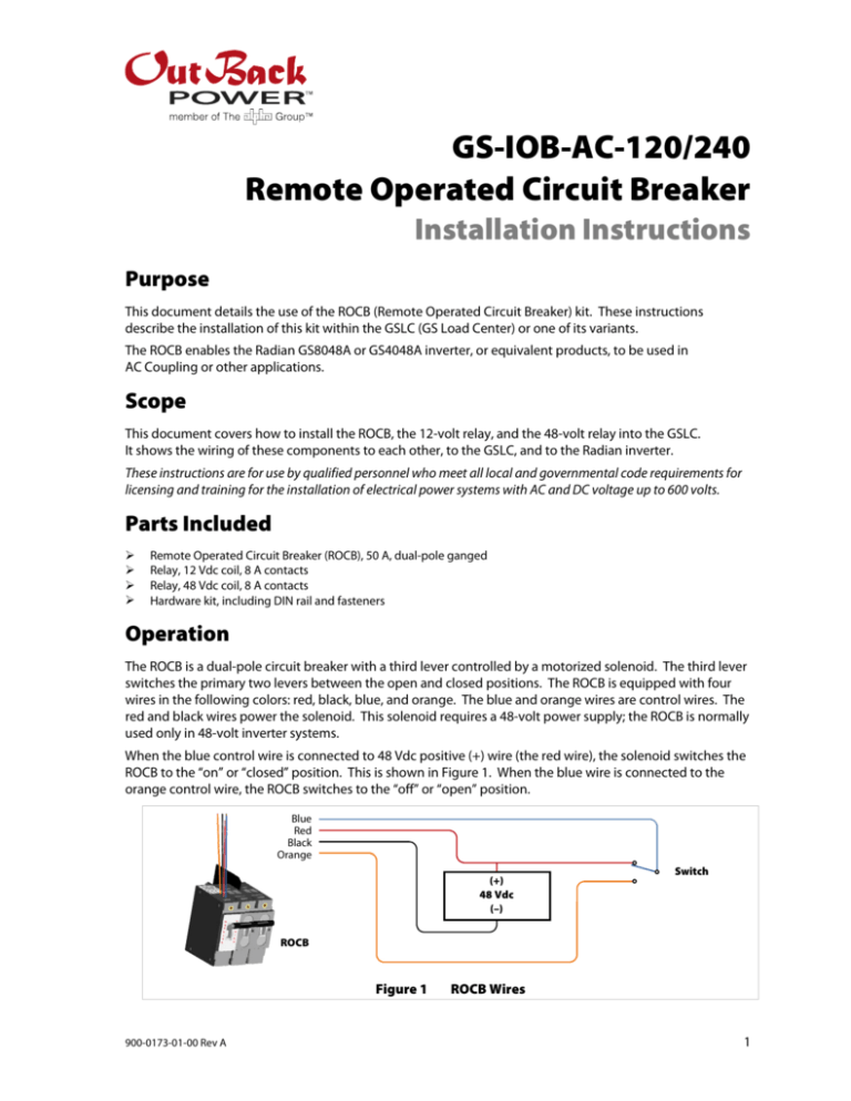
The ROCB is a dual-pole circuit breaker with a third lever controlled by a motorized solenoid. The third lever
switches the primary two levers between the open and closed positions. The ROCB is equipped with four
wires in the following colors: red, black, blue, and orange. The blue and orange wires are control wires. The
red and black wires power the solenoid. This solenoid requires a 48-volt power supply; the ROCB is normally
used only in 48-volt inverter systems.
When the blue control wire is connected to 48 Vdc positive (+) wire (the red wire), the solenoid switches the
ROCB to the “on” or “closed” position. This is shown in Figure 1. When the blue wire is connected to the
orange control wire, the ROCB switches to the “off” or “open” position.
Blue
Red
Black
Orange
(+)
48 Vdc
(–)
Switch
ROCB
Figure 1
900-0173-01-00 Rev A
ROCB Wires
1
Radian Series
Figure 1 shows a basic switch controlling the blue wire, but the switching function can be controlled by
relays or other mechanisms. The relays provided in this kit are intended for this function. Note that the
12-volt relay can be powered by the 12 Vdc Auxiliary output from OutBack devices, but the 48-volt relay and
the ROCB require a 48 Vdc source.
The ROCB kit can be used for AC coupling, load shedding, and other applications where remote-controlled
or automatic disconnection of AC power is a requirement.
Figure 2 is an example of a single-inverter system connected for AC coupling with utility grid service and a
grid-tied (batteryless) inverter. The system shown here has an automatically started generator for backup.
The OutBack Radian-class (GS) inverter is used for AC coupling. Stacked, multiple-inverter systems are also
possible with the same connections.
The Radian inverter sends excess AC-coupled power to the batteries. When too much excess is present, the
relays will disconnect the grid-tied inverter to prevent battery overcharge. The 48-volt relay is also part of
the generator starting circuit and will lock out the grid-tied inverter to prevent a connection or backfeed to
the generator. If a generator is not used in this system, the 48-volt relay may be omitted.
NOTE: These relays are switched by external voltage-controlled hardware such as the 12V AUX and RELAY
AUX terminals in the Radian inverter. (For more information, see the applications note entitled “Adding the
Battery Back-Up Power Option to Existing Grid-Tied PV/Solar Systems” at www.outbackpower.com.)
Other AC-coupled inverters can be used besides the Radian-class. Figure 2 does not show specific inverter
or auxiliary terminal wiring for this reason. System-wide ground and neutral wires have also been omitted
for simplicity. If other inverters are used, two auxiliary controls must be present to provide these functions.
AC-Coupled Inverter
Utility Panel
Load Panel
AC
Grid
L1
Gen
L1
(+)
Switched 12V
L2
L2
AC
Out
L1
Dry Contact
(–)
L2
Grid-Tied Inverter
Relay
(48-volt)
Relay
(12-volt)
ROCB
Generator
Panel
Battery (+) and (–)
Generator Start
Figure 2
2
Wiring ROCB for AC Coupling
900-0173-01-00 Rev A
Part Replacement Instructions
GS Inverter
Accessory Terminals
Utility Grid
ROCB
Generator
Grid-Tied
Inverter
Relays
GSLC
Loads
Batteries
Figure 3
Wiring ROCB into GSLC
Figure 3 shows how the ROCB kit connects to an AC-coupled GSLC (GS Load Center).
NOTES:
In Figure 3, AC circuit panels, all ground wires, and wiring between inverter and GSLC have been omitted for
simplicity. (See inverter and GSLC manuals for more information.)
Use a terminal bus bar (TBB) or another approved method whenever connecting multiple wires together.
To install wires in the 12-volt and 48-volt relays: Insert the wire into the appropriate opening as shown in Figure 3.
Insert a narrow screwdriver or similar tool into the corresponding hole next to it. Press straight down to unlock the
latching mechanism.
CAUTION: Equipment Damage
Do not insert the screwdriver into the opening at anything other than a straight angle. Do not attempt to
use it as a lever. Any motion other than straight down could damage the relay.
The connections may vary with the system. The steps should include the following as appropriate for the
individual installation.
To install the ROCB kit in the GSLC:
1.
Install all Radian AC and DC wiring (see manual).
2.
Select the ROCB mounting location. See Figure 3 for the recommended GSLC location. Using the DIN rail as a
template, mark all DIN rail mounting screw locations. Drill all holes for mounting screws.
3.
Using the enclosed fasteners, mount the DIN rail and install the 12-volt and 48-volt relays.
900-0173-01-00 Rev A
3
Radian Series
4.
Mount the ROCB using three knockout positions on the GSLC circuit breaker rail. See Figure 3 for these positions.
5.
Connect ROCB orange wire to terminal 14 on the 12-volt and 48-volt relays.
6.
Connect ROCB red wire to the GSLC positive cable plate using a ring terminal.
7.
Connect ROCB black wire to the negative TBB; also, connect 48-volt relay terminal A2 to the negative TBB.
8.
Connect ROCB blue wire to 48-volt relay terminal 11.
9.
Connect 48-volt relay terminal 12 to 12-volt relay terminal 11.
10. Connect 48-volt relay terminals 21 and 24 to a two-wire generator start circuit.
11. Connect 48-volt relay terminal A1 to one of the Radian AUX RELAY terminals.
12. Connect 12-volt relay terminal 12 to GSLC positive cable plate; also connect it to the other AUX RELAY terminal.
13. Connect 12-volt relay terminals A1 and A1 to Radian 12V+ AUX and 12V– AUX terminals respectively.
14. Connect the grid-tied (batteryless) inverter L1 and L2 to the ROCB circuit breaker terminals.
15. Connect the grid-tied (batteryless) inverter to the GSLC neutral TBB and ground TBB.
Contact Information
Address:
Corporate Headquarters
17825 – 59th Avenue N.E.
Suite B
Arlington, WA 98223 USA
European Office
Hansastrasse 8
D-91126
Schwabach, Germany
Telephone:
+1.360.435.6030
+1.360.618.4363 (Technical Support)
+1.360.435.6019 (Fax)
+49.9122.79889.0
+49.9122.79889.21 (Fax)
Email:
Support@outbackpower.com
Website:
http://www.outbackpower.com
Disclaimer
UNLESS SPECIFICALLY AGREED TO IN WRITING, OUTBACK POWER TECHNOLOGIES:
(a) MAKES NO WARRANTY AS TO THE ACCURACY, SUFFICIENCY OR SUITABILITY OF ANY TECHNICAL OR OTHER
INFORMATION PROVIDED IN ITS MANUALS OR OTHER DOCUMENTATION.
(b) ASSUMES NO RESPONSIBILITY OR LIABILITY FOR LOSS OR DAMAGE, WHETHER DIRECT, INDIRECT, CONSEQUENTIAL
OR INCIDENTAL, WHICH MIGHT ARISE OUT OF THE USE OF SUCH INFORMATION. THE USE OF ANY SUCH INFORMATION
WILL BE ENTIRELY AT THE USER’S RISK.
Notice of Copyright
GS-IOB-120/240 Remote Operated Circuit Breaker Installation Instructions © June 2014 by OutBack Power Technologies.
All Rights Reserved.
Trademarks
OutBack Power, the OutBack Power logo, and Grid/Hybrid are trademarks owned and used by OutBack Power
Technologies, Inc. The ALPHA logo and the phrase “member of the Alpha Group” are trademarks owned and used by
Alpha Technologies Inc. These trademarks may be registered in the United States and other countries.
Date and Revision
June 2014, Revision A
Part Number
900-0173-01-00 Rev A
4
900-0173-01-00 Rev A


