APPLICATION NOTE
Specular Reflectance – Theory and Applications
Specular reflectance sampling in FTIR represents a very important
technique useful for measurement of thin films on reflective
substrates, analysis of bulk materials and measurement of monomolecular layers on a substrate material. Often the specular
reflectance technique provides a means of sample analysis with
no sample preparation – keeping the sample intact for other
measurements.
The basics of the sampling technique involve measurement
of the reflected energy from a sample surface at a given angle of
incidence. The electromagnetic and physical phenomena which
occur at and near the surface are dependent upon the angle of
incidence of the illuminating beam, refractive index and thickness
of the sample and other sample and experimental conditions. A
discussion of all of the physical parameters and considerations
surrounding the specular reflectance sampling technique is
beyond the scope of this overview. We will present the specular
reflectance sampling technique from an applications oriented
perspective.
At the reflective substrate, the beam reflects back to the
surface of the thin film. When the beam exits the thin film it has
geometrically passed through the film twice and is now represented
as IA. Infrared energy is absorbed at characteristic wavelengths as
this beam passes through the thin film and its spectrum is recorded.
The specular reflectance spectra produced from relatively thin
films on reflective substrates measured at near-normal angle of
incidence are typically of high quality and very similar to spectra
obtained from a transmission measurement. This result is expected
as the intensity of IA is high relative to the specular component, IR.
Types of specular reflectance experiments
• Reflection-Absorption of relatively thin films on reflective
substrates measured at near normal angle of incidence
• Specular Reflectance measurements of relatively thick samples
measured at near normal angle of incidence
• Grazing Angle Reflection-Absorption of ultra-thin films or monolayers deposited on surfaces measured at high angle of incidence
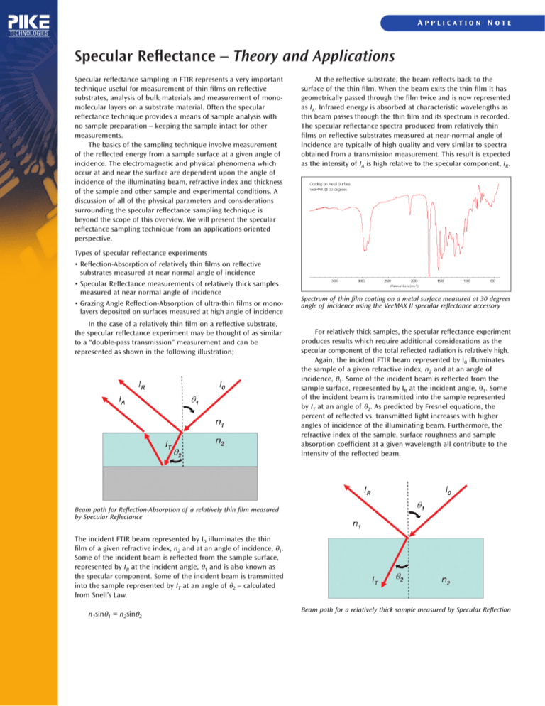
In the case of a relatively thin film on a reflective substrate,
the specular reflectance experiment may be thought of as similar
to a “double-pass transmission” measurement and can be
represented as shown in the following illustration;
Spectrum of thin film coating on a metal surface measured at 30 degrees
angle of incidence using the VeeMAX II specular reflectance accessory
For relatively thick samples, the specular reflectance experiment
produces results which require additional considerations as the
specular component of the total reflected radiation is relatively high.
Again, the incident FTIR beam represented by I0 illuminates
the sample of a given refractive index, n2 and at an angle of
incidence, θ1. Some of the incident beam is reflected from the
sample surface, represented by IR at the incident angle, θ1. Some
of the incident beam is transmitted into the sample represented
by IT at an angle of θ2. As predicted by Fresnel equations, the
percent of reflected vs. transmitted light increases with higher
angles of incidence of the illuminating beam. Furthermore, the
refractive index of the sample, surface roughness and sample
absorption coefficient at a given wavelength all contribute to the
intensity of the reflected beam.
Beam path for Reflection-Absorption of a relatively thin film measured
by Specular Reflectance
The incident FTIR beam represented by I0 illuminates the thin
film of a given refractive index, n2 and at an angle of incidence, θ1.
Some of the incident beam is reflected from the sample surface,
represented by IR at the incident angle, θ1 and is also known as
the specular component. Some of the incident beam is transmitted
into the sample represented by IT at an angle of θ2 – calculated
from Snell’s Law.
n1sinθ1 = n2sinθ2
Beam path for a relatively thick sample measured by Specular Reflection
At wavelengths where the sample exhibits a strong IR absorption,
the reflectivity of the sample increases. The superposition of the
extinction coefficient spectrum with the refractive index dispersion
results in a spectrum with derivative shaped bands. This specular
reflection spectrum can be transformed using a Kramers-Kronig
conversion to a transmission-like spectrum as shown in the
example below.
Because of the orientation of the electro-magnetic field at
the surface for grazing angle measurements, the use of an IR
polarizer greatly improves the sampling result. By collecting the
spectrum at grazing angle of incidence with P-polarization, we
only examine the enhanced portion of the electromagnetic field
at the sample surface, thereby producing a stronger absorbance
spectrum.
Spectrum (upper – original) of a relatively thick polymer sample measured
at 30 degrees angle of incidence using the VeeMAX II. The lower spectrum
has been transformed using the Kramers-Kronig software algorithm and
is very similar to a transmission spectrum of the polymer – polyethylene.
Grazing angle specular reflection analysis of a thiol mono-molecular layer
deposited on a gold surfaced mirror using the PIKE VeeMAX II at 80 degrees
and P-polarization. The FTIR was equipped with an MCT detector.
Our third application of specular reflectance is the measurement of relatively thin films and mono-molecular layers at grazing
angle of incidence. At high angles of incidence, between 60 and
85 degrees, the electromagnetic field in the plane of the incident
and reflected radiation is greatly increased relative to a near normal
angle of incidence. The perpendicular component of the electromagnetic field of the reflecting radiation is not enhanced.
Specular reflectance is a valuable FTIR sampling technique
for the analysis of thin films on reflective substrates, for the
analysis of relatively thick films on reflective materials and for
analysis of bulk materials where no sample preparation is
preferred. PIKE Technologies offers a complete line of specular
reflectance accessories and options to do these analysis and
perform these experiments.
Grazing angle specular reflection analysis produces a strong electromagnetic field oriented in the plane of the incident and reflected radiation
6125 Cottonwood Drive Madison, WI 53719 • (608) 274-2721 • (608) 274-0103 (FAX) • www.piketech.com • sales@piketech.com (E-MAIL)
©2011 PIKE Technologies. All rights reserved. All trademarks are the property of PIKE Technologies.

