CONSTRUCTION APPLICATION GUIDE HOW TO SELECT AN RC
advertisement
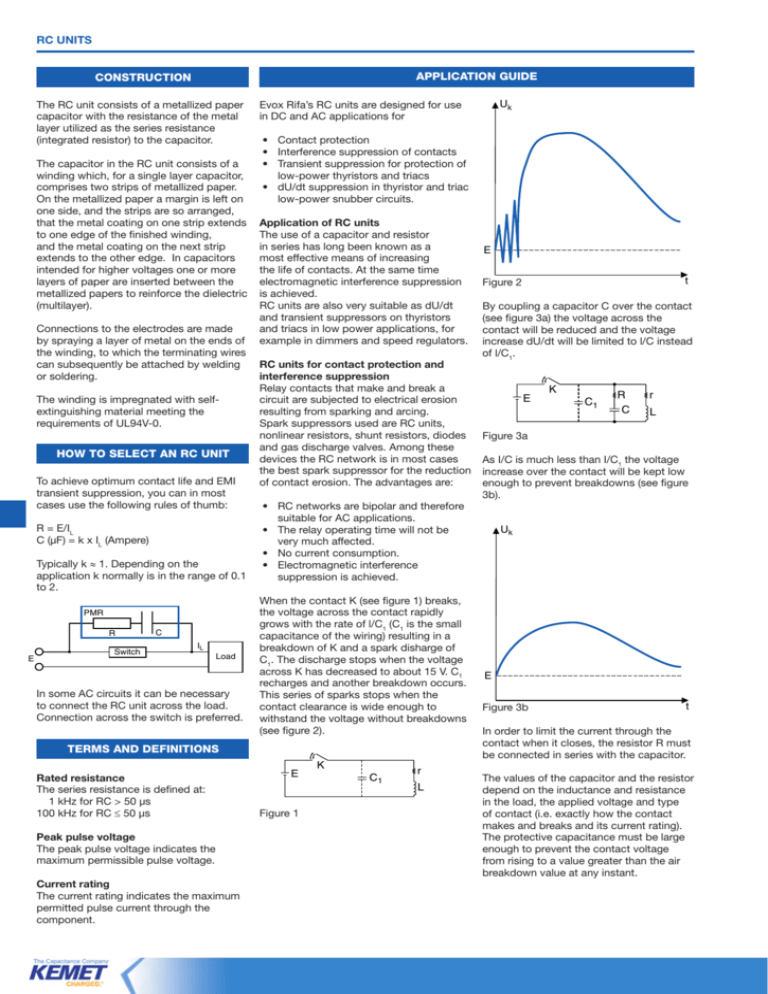
rc units Application guide Construction The RC unit consists of a metallized paper capacitor with the resistance of the metal layer utilized as the series resistance (integrated resistor) to the capacitor. The capacitor in the RC unit consists of a winding which, for a single layer capacitor, comprises two strips of metallized paper. On the metallized paper a margin is left on one side, and the strips are so arranged, that the metal coating on one strip extends to one edge of the finished winding, and the metal coating on the next strip extends to the other edge. In capacitors intended for higher voltages one or more layers of paper are inserted between the metallized papers to reinforce the dielectric (multilayer). Connections to the electrodes are made by spraying a layer of metal on the ends of the winding, to which the terminating wires can subsequently be attached by welding or soldering. The winding is impregnated with selfextinguishing material meeting the requirements of UL94V-0. How to select an RC unit To achieve optimum contact life and EMI transient suppression, you can in most cases use the following rules of thumb: R = E/IL C (µF) = k x IL (Ampere) Typically k ≈ 1. Depending on the application k normally is in the range of 0.1 to 2. PMR R E Switch C IL Load In some AC circuits it can be necessary to connect the RC unit across the load. Connection across the switch is preferred. • • • • Contact protection Interference suppression of contacts Transient suppression for protection of low-power thyristors and triacs dU/dt suppression in thyristor and triac low-power snubber circuits. Application of RC units The use of a capacitor and resistor in series has long been known as a most effective means of increasing the life of contacts. At the same time electromagnetic interference suppression is achieved. RC units are also very suitable as dU/dt and transient suppressors on thyristors and triacs in low power applications, for example in dimmers and speed regulators. RC units for contact protection and interference suppression Relay contacts that make and break a circuit are subjected to electrical erosion resulting from sparking and arcing. Spark suppressors used are RC units, nonlinear resistors, shunt resistors, diodes and gas discharge valves. Among these devices the RC network is in most cases the best spark suppressor for the reduction of contact erosion. The advantages are: • • • • RC networks are bipolar and therefore suitable for AC applications. The relay operating time will not be very much affected. No current consumption. Electromagnetic interference suppression is achieved. When the contact K (see figure 1) breaks, the voltage across the contact rapidly grows with the rate of l/C1 (C1 is the small capacitance of the wiring) resulting in a breakdown of K and a spark disharge of C1. The discharge stops when the voltage across K has decreased to about 15 V. C1 recharges and another breakdown occurs. This series of sparks stops when the contact clearance is wide enough to withstand the voltage without breakdowns (see figure 2). Terms and definitions Rated resistance The series resistance is defined at: 1 kHz for RC > 50 µs 100 kHz for RC ≤ 50 µs Peak pulse voltage The peak pulse voltage indicates the maximum permissible pulse voltage. Current rating The current rating indicates the maximum permitted pulse current through the component. Uk Evox Rifa’s RC units are designed for use in DC and AC applications for E Figure 1 K C1 r L E t Figure 2 By coupling a capacitor C over the contact (see figure 3a) the voltage across the contact will be reduced and the voltage increase dU/dt will be limited to l/C instead of l/C1. E K C1 R C r L Figure 3a As I/C is much less than I/C1 the voltage increase over the contact will be kept low enough to prevent breakdowns (see figure 3b). Uk E Figure 3b t In order to limit the current through the contact when it closes, the resistor R must be connected in series with the capacitor. The values of the capacitor and the resistor depend on the inductance and resistance in the load, the applied voltage and type of contact (i.e. exactly how the contact makes and breaks and its current rating). The protective capacitance must be large enough to prevent the contact voltage from rising to a value greater than the air breakdown value at any instant. rc units Application guide This value depends on the contact separation but is never less than 300 volts. With few exceptions, a 0.1 µF capacitor will be large enough to hold the peak voltage to less than 300 volts. Limiting the voltage rise across the contacts to less than 300 volts peak will not necessarily prevent all breakdowns of the gap. At the very first instant of contact breaking the contact operation is so minute that low-voltage breakdowns of the gap may occur. To minimize this risk the common procedure is to impose the additional requirement that the contact protection capacitor must limit the rate of voltage rise immediately after the contact breaks to 1 volt per microsecond. This requirement will be met if the ratio l/C is less than unity where I is given in amperes and C is in microfarads. For slow moving contacts even larger capacitors are used. With sufficient capacitance in the circuit for protection when the contact breaks, a resistor is needed for protection when the contact closes. The network capacitor is charged to the full voltage when the circuit is open. Closing the contacts effectively short-circuits this voltage, so a resistance is connected in series with the network capacitor to limit the current through the contact. The resistor thus reduces erosion as the contact closes, but also tends to increase it as it opens. The sudden diversion of the steady-state current into the protection network on contact breaking immediately produces a voltage across the contacts due to the current flowing through the protection resistance. A compromise is therefore necessary, and it is general practice to have a resistance that gives the same current through the contact on closure as the steady-state current. The RC network can be connected across the contact or across the load. If there is long wiring between the contact and the load, connecting the RC network across the contact is to be preferred. Load ~E L R C1 R C Figure 4a supply voltage A At the same time as the contact is protected by the RC network, electromagnetic interference suppression is achieved as the sparks, which contain a high frequency spectrum are avoided. RC units as dU/dt suppressors on thyristors and triacs The junctions of any semiconductor exhibit some unavoidable capacitance. A changing voltage impressed on this junction capacitance results in a current, I = C dU/dt. If this current is sufficiently large a regenerative action may occur causing the SCR to switch to the on-state. This regenerative action is similar to what will occur when a gate current is injected. High dU/dt may occur from other thyristors switching on or off or be due to reapplied dU/dt. Figure 4a shows a full-wave phase control circuit, with an inductive load. When the current decreases to zero (the triac commutates, point A), figure 4b, the supply voltage (which is not zero) must then appear as a forward bias across the triac. The rate-of-change of this voltage is dependent on inductance and capacitance in the load circuit, as well as on reverse commutation point load current voltage across triac A dU/dt overshoot Figure 4b recovery characteristics of the triac. The application of a series RC circuit in parallel with the triac will reduce the dU/dt to an acceptable value. The values of R and C are functions of the load, line voltage and triac used. Since circuit impedances for a particular application are not usually well known the values of C and R are often determined by trial and error, or simply by overrating. For triacs 0.1 µF + 100 Ω is often used. Evox Rifa’s RC units are well suited as dU/dt protectors in low power circuits. As the tolerances of capacitance and resistance are not critical they will give satisfactory operation in most circuits. Evox Rifa Leaded Film Capacitors 83


