Ammeters & Voltmeters RC – Circuits
advertisement
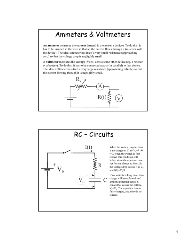
Ammeters & Voltmeters An ammeter measures the current (Amps) in a wire (or a device). To do this, it has to be inserted in the wire so that all the current flows through it (in series with the device). The ideal ammeter has itself a very small resistance (approaching zero) so that the voltage drop is negligibly small. A voltmeter measures the voltage (Volts) across some other device (eg, a resistor or a battery). To do this, it has to be connected across (in parallel) to that device. The ideal voltmeter has itself a very large resistance (approaching infinite) so that the current flowing through it is negligibly small. RV A R(i) V RC – Circuits I(t) + When the switch is open, there is no charge on C, so Vc=0. At t=0, when the switch is first closed, this condition still holds, since there was no time yet for any charge to flow. So the voltage drop across R is V0 and I(0)=V0/R. R V0 VC C If we wait for a long time, then charge will have flowed to C until the potential across C equals that across the battery, Vc=V0. The capacitor is now fully charged, and there is no current. 1 RC – Circuits II What happens between t=0 and t very large? Charge will flow at a rate of i(t)=dq/dt from the battery through the resistor to the capacitor. The voltage across the capacitor will be V=q/C. We can write the circuit equation (going around the loop) as: q dq q = 0 ⇒ V0 − R − = 0 ⇒ C dt C V0 dq 1 + q= dt RC R V0 − iR − This is a differential equation, which has a solution in the general form: q = A + Be ( −t RC ) A and B are constants which we determine from the initial conditions: At t=0, q=0, from which we learn that 0=A+B, so B=-A, and at t=∞ Vc=q/C=V0 so we must have q=V0C=A+0, thus A=V0C. The solution for a charging capacitor is thus: ( −t ) q = V0C 1 − e RC RC-Circuits III A charging capacitor thus has a time dependent charge on it that follows the equation: q The voltage across the capacitor is just V(t)=q/C, which gives: To get the time dependent current we differentiate q(t) wrt. t, which gives: ( t ) = V0C 1 − e( V ( t ) = V0 1 − e i (t ) = −t RC ) ( − t RC ) V0 ( − t RC ) e R The term RC has units of seconds, and is called the time constant, τ. After one time constant (t= τ) the capacitor will have charged to 1-e-1=63% maximum value and the current will have dropped from I0=V0/R to 1/e=37% of that value. 2 RC-Circuits IV A discharging capacitor has fairly similar equations. The solutions are: I(t) q ( t ) = V0Ce V ( t ) = V0 e R VC C i (t ) = ( −t RC ) ( −t RC ) −V0 ( − t RC ) e R 3

![Sample_hold[1]](http://s2.studylib.net/store/data/005360237_1-66a09447be9ffd6ace4f3f67c2fef5c7-300x300.png)
