1121283 - Battery Box & Trickle Charger SMARTwire.indd - Shur-Co
advertisement
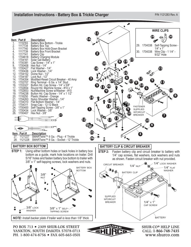
Installation Instructions - Battery Box & Trickle Charger P/N 1121283 Rev. A WIRE CLIPS 11 Item 1. 2. 3. 4. 5. 6. 7. 8. 9. 10. 11. 12. 13. 14. 15. 16. 17. 18. 19. 20. 21. 22. 23. 24. 25. 26. Part # 1119783 1117734 1117740 1117739 1117741 1704618 1704161 1700381 1700408 1700427 1700436 1704152 1704187 1704354 1702707 1703327 1702654 1702653 1704238 1118250 1704263 1704310 1704311 1700400 1700434 1700407 30 29 16 Description Battery Box Bottom - Trickle Battery Box Top Battery Box Hold-Down Bracket Battery Box Front Bracket Battery Clip Battery Charging Module Solar Gel Battery Cap Screw - 1/4” x 1” Hex Nut - 1/4” Flat Washer - 1/4” Lock Washer - 1/4” Dome Nut - 1/2” Lock Nut - 1/2” Modified-Reset Circuit Breaker - 40 Amp Ring Terminal - 6 Ga. x 1/4” Stud Button Hd. Cap Screw - 1/4” x 5/8” Round Hd. Machine Screw - #10 x 1” Nut/Machine Screw w/Washer - #10 Button Hd. Cap Screw - 1/4” x 1 1/2” Plastic Washer - Orange Nylon Shoulder Washer - 1/4” Flat Bottom Washer - 1/4” Snap-Cap - 12-12 Black Self-Tapping Screw - 3/8” x 1” Lock Washer - 3/8” Hex Nut - 3/8” 27 29. 1704338 Self-Tapping Screw 1/4” x 1” 30. 1704338 Wire Clip - 1 1/4” 9/32” Hole 2 8 19 10 23 15 18 22 6 3 21 9 17 9 11 20 9 11 9 10 11 5 10 8 14 24 10 1 12 11 13 9 10 FASTENER SUPPLIED W/CIRCUIT BREAKER 11 7 10 8 28 Item Part # Description 27. 1121227 SMARTwire™ 6 Ga. - Plug - 4’ Trickle 28. 1121228 SMARTwire™ 6 Ga. - Socket - 12’ Trickle 25 4 26 BATTERY BOX BOTTOM STEP 1: Using either bottom holes or back holes in battery box bottom as a guide, mark hole locations on trailer. Drill 5/16” holes and fasten battery box bottom to trailer with 3/8” x 1” self-tapping screws, lock washers and nuts. BATTERY CLIP & CIRCUIT BREAKER STEP 2: Fasten battery clip and circuit breaker to battery with 1/4” cap screws, flat washers, lock washers and nuts as shown. Fasten circuit breaker with nut provided. CIRCUIT BREAKER BATTERY BOX BOTTOM 1/4” NUT 1/4” LOCK WASHER 1/4” FLAT WASHER BATTERY CLIP 3/8” NUT SUPPLIED W/CIRCUIT BREAKER 3/8” LOCK WASHER 1/4” X 1” CAP SCREW 3/8” X 1” SELFTAPPING SCREW NOTE: Install backer plate if trailer wall is less than 1/8” thick. BATTERY Installation Instructions - Battery Box & Trickle Charger P/N 1121283 Rev. A BATTERY & BRACKETS STEP 5: DOME NUTS & HOLD-DOWN BRACKETS STEP 3: Secure dome nut strain reliefs to battery box bottom with 1/2” lock nuts. Place battery in battery box bottom. Install hold-down bracket and front bracket with 1/4” x 1” cap screws, flat washers, lock washers and nuts. 1/4” X 1” CAP SCREW HOLD-DOWN BRACKET/ BATTERY CHARGING MODULE ASSEMBLY 1/4” FLAT WASHER BATTERY BOX BOTTOM BATTERY 1/4” LOCK WASHER 1/4” 1/4” NUT FLAT WASHER DOME NUT 1/2” LOCK NUT BATTERY BOX BOTTOM FRONT BRACKET BATTERY CHARGING MODULE STEP 4: Fasten battery charging module to hold-down bracket with #10 x 1” machine screws and nut/washers. Install 1/4” x 1 1/2” button head cap screw, flat bottom washer, shoulder washers, orange plastic washer, flat washer, hex nut, lock washer, second hex nut and snap cap as shown. #10 NUT/WASHER 1/4” NYLON SHOULDER WASHER 1/4” X 1 1/2” SNAP CAP BATTERY BOX TOP STEP 6: NOTE: Go to wiring instructions on next page. Secure battery box top to battery box bottom with 1/4” x 5/8” cap screws and lock washers. BATTERY BOX TOP 1/4” LOCK 1/4” X 1” CAP SCREW 1/4” X 5/8” BUTTON HEAD CAP SCREW WASHER BUTTON HD CAP SCREW HOLD-DOWN BRACKET 1/4” FLAT BOTTOM WASHER ORANGE PLASTIC WASHER 1/4” FLAT 1/4” WASHER 1/4” HEX NUT HEX 1/4” LOCK NUT WASHER BATTERY CHARGING MODULE #10 X 1” MACHINE SCREW FULLY ASSEMBLED BATTERY BOX BOTTOM ASSEMBLY Installation Instructions - Battery Box & Trickle Charger P/N 1121283 Rev. A TRUCK BATTERY Item 1. 2. 3. Part # 1120670 1121227 1121228 Description SMARTwire™ Dual-Conductor Socket SMARTwire™ 6 Ga. - Plug - 4’ Trickle SMARTwire™ 6 Ga. - Socket - 12’ Trickle BATTERY CHARGING MODULE JUNCTION POST DUALCONDUCTOR PLUG POSITIVE WIRE (RED W/ 1/4” RING TERMINAL) 1 POSITIVE WIRE (RED W/ #10 RING TERMINAL) 2 NEGATIVE WIRE (BLACK) NEGATIVE WIRE (1/4” RING TERMINAL) CIRCUIT BREAKER POSITIVE WIRE (RED OR RED STRIPE) TRAILER BATTERY NEGATIVE WIRE (BLACK) 3 POSITIVE WIRE (RED OR RED STRIPE) TO JUNCTION BLOCK, JUNCTION BOX OR MOTOR CONTROLS MASTER DISCONNECT WIRING NOTE: Connect circuit breaker after completing step 1. STEP 1: Route ring terminal ends of 2 wire through dome nuts into battery box. Connect positive lead from 2 and red wire from battery charging module with 1/4” ring terminal to junction post. Connect negative lead from 2 and black wire from battery charging module to negative trailer battery post. Connect red wire with #10 ring terminal from battery charging module to circuit breaker post near terminal. STEP 2: Route ring terminal ends of 3 through dome nuts into battery box. Connect negative lead of 3 to negative post on trailer battery. Connect positive lead of 3 to circuit breaker post farthest from battery terminal. STEP 3: For outgoing load wire 3 , route to load as desired but do not fasten down yet. Locate desired mounting position for master disconnect switch and install switch before securing wire. Installation Instructions - Battery Box & Trickle Charger P/N 1121283 Rev. A 1 5 Item 1. 2. 3. 4. 5. 6. 7. 8. 9. Part # 1704405 1704283 1703244 1704330 1118556 1704187 1704152 1121094 Description Self-Drilling Screw - #8 x 3/4” Master Battery Disconnect Switch Ring Terminal - 6 Ga. x 3/8” Stud Rubber Boot Solar Master Disconnect Box Lock Nut - 1/2” Dome Nut - 1/2” SMARTwire™ - 6 Ga. Socket - 12’ (not shown) 1704284 Face Plate - Rotary Switch STEP 1: SCREWS SUPPLIED W/SWITCH 6 4 7 2 WIRE CLIPS 11 10 3 10. 1704338 Self-Tapping Screw 1/4” x 1” 11. 1704338 Wire Clip - 1 1/4” 9/32” Hole 9 Route wire (P/N 1121094) along planned route. Determine desired location of master disconnect switch along wire route. Cut positive half of this wire at mounting location. Do not cut negative wire. Carefully peel positive side of wire away from negative side about 1” on either side of cut. STEP 4: Connect wires to master disconnect switch. Coat with dielectric grease and install rubber boots over ring terminals. MASTER DISCONNECT SWITCH MASTER DISCONNECT BOX #8 X 1/2” STEP 2: STEP 3: SCREW (SUPPLIED) Unfasten screws and remove cover/ switch assembly from master disconnect box. RING TERMINALS RUBBER BOOTS STEP 5: COVER/SWITCH ASSEMBLY Run positive 6-ga. wire ends through dome nuts on master disconnect box. Run wire ends through rubber boots and crimp 3/8” ring terminals to ends of wire. DOME NUT MASTER DISCONNECT BOX WIRE Re-install cover/switch assembly to master disconnect box. Fasten with supplied #8 x 1/2” screws. #8 X 1/2” SCREW (SUPPLIED) COVER/SWITCH ASSEMBLY STEP 6: RUBBER BOOT MASTER DISCONNECT BOX Fasten master disconnect switch box to trailer with four #8 x 3/4” self-drilling screws. WIRE RING TERMINAL NOTE: Cut wires to length and strip only enough wire insulation to install ring terminals. Insert bare wire into ring terminals and crimp securely. MASTER DISCONNECT SWITCH STRIP WIRE INSULATION RING TERMINAL STEP 7: CRIMP SECURELY #8 X 3/4” SELF-DRILLING SCREWS Secure wire (P/N 1121094) with wire clips tapping screws 10 . 11 and self-
