Drilling: Geological Issues
Drilling
Geol493K
•
•
•
•
•
•
•
•
•
•
Drilling Process and Components
Rotary system
Mud system
Well side geology
Well completion- Casing & Cement
Well coring, side wall cores
Off shore drilling
Horizontal drilling
Frac’ing
Deepwater Horizon disaster
2
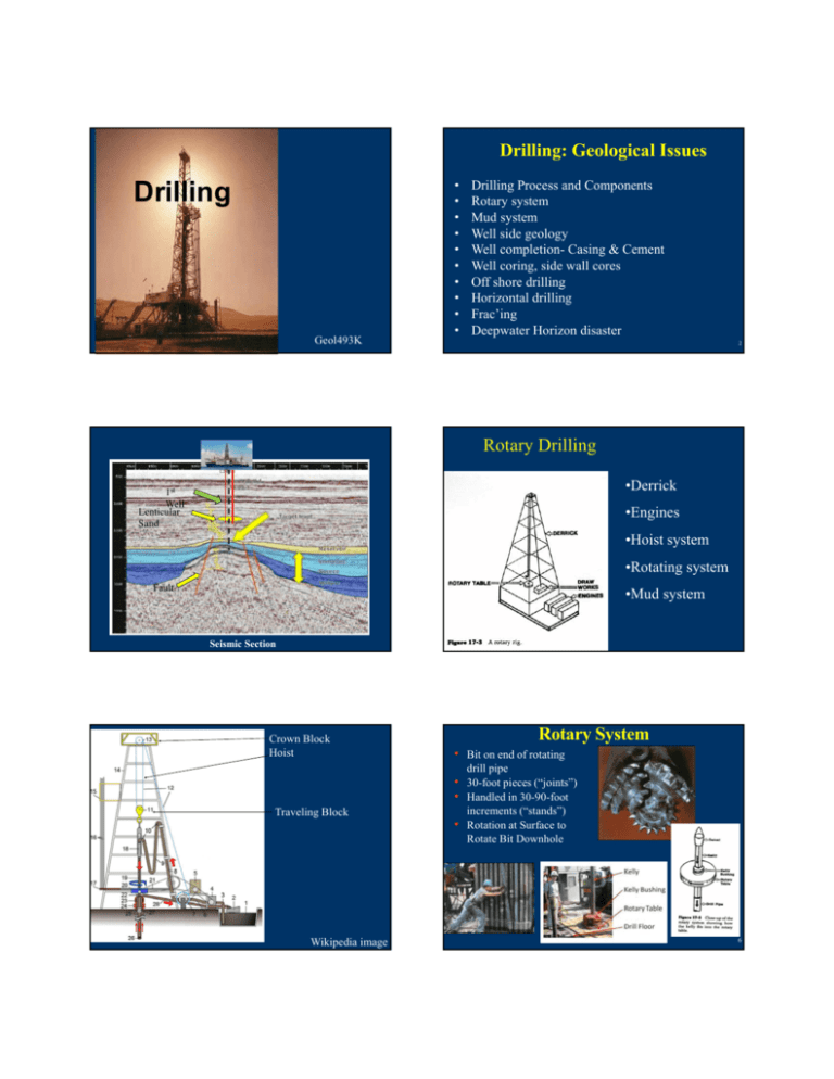
Rotary Drilling
•Derrick
1st
Well
Lenticular
Sand
•Engines
•Hoist system
•Rotating system
Fault
•Mud system
Seismic Section
Crown Block
Hoist
Rotary System
• Bit on end of rotating
drill pipe
• 30-foot pieces (“joints”)
• Handled in 30-90-foot
Traveling Block
increments (“stands”)
• Rotation at Surface to
Rotate Bit Downhole
Wikipedia image
6
Down hole
hammer bit
- Percussion
drilling
Drill pipe
Drilling Rates
•Sandstones are fast
•Limestone/dolomite
can be slow
•Shales are slow
Drilling Mud System
Drilling Mud
Purpose/Role
• Maintain sufficient bottomhole pressure
• Flush cuttings from beneath
bit and upward out of hole
• Cool bit (and drill string)
•Can be used to
identify formation
tops
10
Drilling Mud
Well Cuttings
• Bentonite (clay)
• Barite (BaSO4)
Wellside Geologists
9-10 lb/gal
15-20 lb/gal
• Water based mud
• Oil based mud- used to avoid problems with
swelling clays (montmorillenite)
Issue: Mud Damage to Reservoir
Drilling Mud-Environmental Issues
UV fluorecense
Unlined Mud Pit
3061.50m
Mud invasion
on fractures?
Fractures
drilling-induced
or natural?
Pit with oil in it
Flags to keep
migratory birds
off
US Fish & Wildlife Photos
Blow out
Preventers
Deepwater
Horizon
BOP
New York Times
Casing and Cement
Well completion
Key decision
during
exploration
Isolating an overpressure zone
CORING ASSEMBLY AND CORE BIT
Oil-Saturated Core, off shore Brazil
Drill collar
connection
PDC Cutters
Thrust bearing
Outer barrel
Inner barrel
Fluid
vent
Core retaining
ring
Core bit
WHOLE CORE
SIDEWALL SAMPLING GUN
Whole Core Photograph,
Misoa “C” Sandstone,
Venezuela
Core bullets
Formation rock
Core sample
Photo by W. Ayers
SIDEWALL CORING TOOL
Coring bit
Samples
Sidewall Cores
Offshore Drilling Rigs
Floating Production and Storage
Platform
Santa Barbara, CA
North Sea
25
Types of offshore oil and gas structures
Top View
How Vertical are “Vertical
Wells”?
Side Views
ESSO PAREX ET AL KYLE L-11
East-west
1,2) Conventional fixed platforms (1,353 ft); 3) compliant tower (1,754
ft GOM); 4,5) Vertically moored tension leg platform (4,674 ft); 6) Spar
(5,610 ft); 7,8) Semi-submersibles (6,300 ft); 9) Floating production,
storage, and offloading facility (4,429 ft ); 10) Sub-sea completion and
tie-back to host facility (7,570 ft.) (2005 depth records) NOAA image
Horizontal Drilling
Components
North-south
Natural
Resources
Canada
DOWN HOLE MUD MOTORS
PowerPak - steerable PDM
(Schlumberger)
World record (2011) 11 km horizontal reach
Top View
Horizontal Well Layout
Logging-while Drilling tools
Side View
•
Directional data (inclination, azimuth, tool-face)
•
Formation characteristics (gamma-ray, resistivity
logs, etc)
•
Drilling parameters ( down-hole WOB, torque, rpm)
2500 ft
1000 ft
© 2010 MicroSeismic. All Rights Reserved.
Geosteering
Geometry of Geosteering pt 1
Vertical Log
Tie Point
LWD
Well trajectory
Marcellus (green)
Well Path
Gamma Ray Log
Frac’ing a Well
Perforating a well – Shaped charges
Concrete target
© 2010 MicroSeismic. All Rights Reserved.
Baumann et al. 2014
Frac Parameters
Slurry Rate
Hydraulic fracturing in a wellbore
Time (hours)
Pressure
Propant
Hydraulic Fracturing
SH is maximum horizontal stress
Seismic Events
© 2010 MicroSeismic. All Rights Reserved.
Sh is minimum horizontal stress
Zoback , 2010
Microseismic Monitoring of Frac Job
Plexiglass Fracture
Fracture surface in Plexiglas with fracture propagation
textures (Pollard and Fletcher, 2005)
7 Well Frac
Earthquakes scaled by magnitude
colors by stage
© 2010 MicroSeismic. All Rights Reserved.
DeepWater Horizon Spill
Read: Accident Report on Ecampus
© 2010 MicroSeismic. All Rights Reserved.


