The Silicon Controlled Rectifier
advertisement
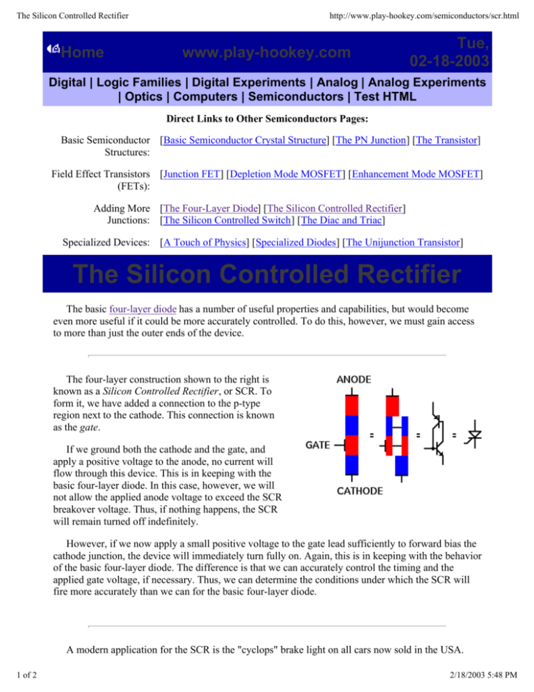
The Silicon Controlled Rectifier Home http://www.play-hookey.com/semiconductors/scr.html www.play-hookey.com Tue, 02-18-2003 Digital | Logic Families | Digital Experiments | Analog | Analog Experiments | Optics | Computers | Semiconductors | Test HTML Direct Links to Other Semiconductors Pages: Basic Semiconductor [Basic Semiconductor Crystal Structure] [The PN Junction] [The Transistor] Structures: Field Effect Transistors [Junction FET] [Depletion Mode MOSFET] [Enhancement Mode MOSFET] (FETs): Adding More [The Four-Layer Diode] [The Silicon Controlled Rectifier] Junctions: [The Silicon Controlled Switch] [The Diac and Triac] Specialized Devices: [A Touch of Physics] [Specialized Diodes] [The Unijunction Transistor] The Silicon Controlled Rectifier The basic four-layer diode has a number of useful properties and capabilities, but would become even more useful if it could be more accurately controlled. To do this, however, we must gain access to more than just the outer ends of the device. The four-layer construction shown to the right is known as a Silicon Controlled Rectifier, or SCR. To form it, we have added a connection to the p-type region next to the cathode. This connection is known as the gate. If we ground both the cathode and the gate, and apply a positive voltage to the anode, no current will flow through this device. This is in keeping with the basic four-layer diode. In this case, however, we will not allow the applied anode voltage to exceed the SCR breakover voltage. Thus, if nothing happens, the SCR will remain turned off indefinitely. However, if we now apply a small positive voltage to the gate lead sufficiently to forward bias the cathode junction, the device will immediately turn fully on. Again, this is in keeping with the behavior of the basic four-layer diode. The difference is that we can accurately control the timing and the applied gate voltage, if necessary. Thus, we can determine the conditions under which the SCR will fire more accurately than we can for the basic four-layer diode. A modern application for the SCR is the "cyclops" brake light on all cars now sold in the USA. 1 of 2 2/18/2003 5:48 PM The Silicon Controlled Rectifier http://www.play-hookey.com/semiconductors/scr.html This circuit uses two SCRs cross-connected with each other (each gate connected to the other SCR's anode) and triggered from the regular brake lights on either side of the rear of the vehicle. The lights are connected to the two cathodes, which are connected together so that either SCR can keep both lights on once they are triggered. If only one SCR is triggered (as when you use a turn signal), the triggered SCR gets no anode voltage from the opposite tail light, so the "cyclops" light remains off. Only if both tail lights are on together will the "cyclops" turn on. Once it does, it remains on regardless of turn signals as long as the brake is applied. When you release the brake, power is removed from the "cyclops" as well as from the tail lights and they all turn off. Another practical application is in a telephone "hold" circuit. Triggering the SCR causes the circuit to contiuously draw current through the telephone wires, thus causing the switching station to assume a phone is still in use. Picking up another receiver in the house reduces the current through the SCR enough that it turns off. All pages on www.play-hookey.com copyright © 1996, 2000-2002 by Ken Bigelow Please address queries and suggestions to: webmaster@play-hookey.com 2 of 2 2/18/2003 5:48 PM

