Moore versus Mealy Specifying outputs
advertisement
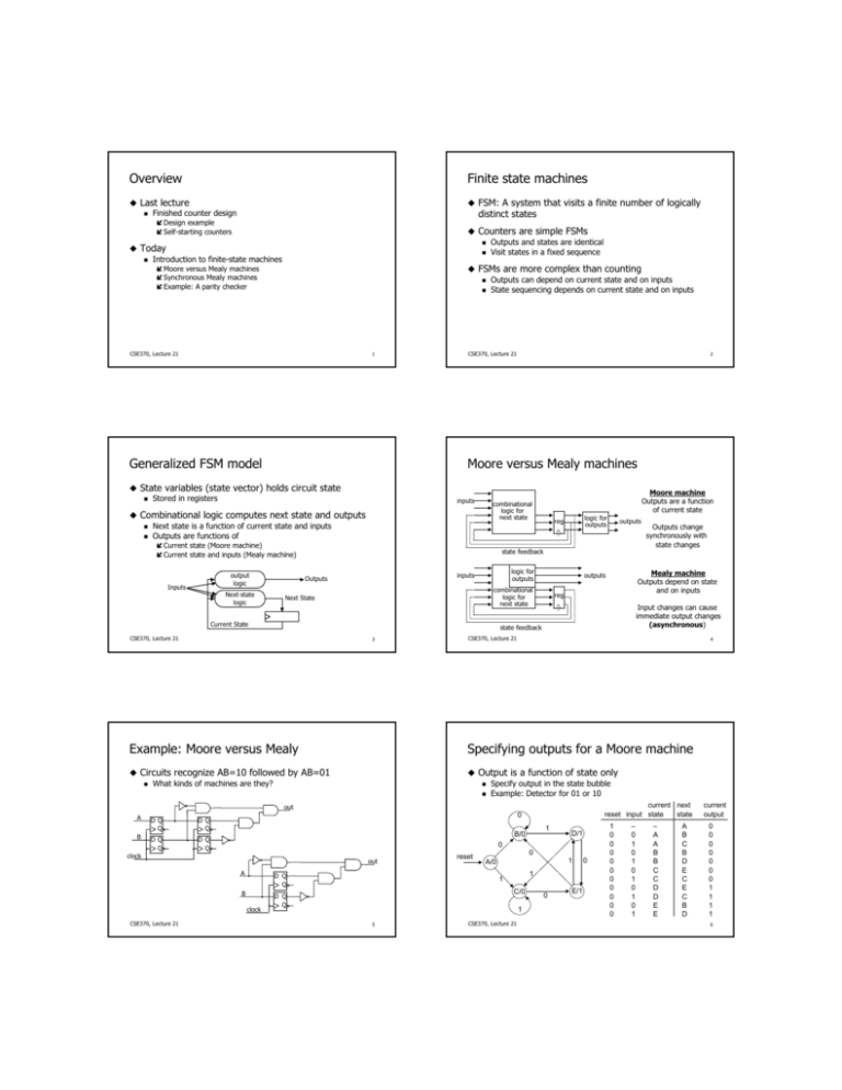
Overview Finite state machines ! Last lecture " Finished counter design ! FSM: A system that visits a finite number of logically distinct states # Design example # Self-starting counters ! Counters are simple FSMs " Outputs and states are identical " Visit states in a fixed sequence ! Today " Introduction to finite-state machines ! FSMs are more complex than counting " Outputs can depend on current state and on inputs " State sequencing depends on current state and on inputs # Moore versus Mealy machines # Synchronous Mealy machines # Example: A parity checker CSE370, Lecture 21 1 Generalized FSM model CSE370, Lecture 21 Moore versus Mealy machines ! State variables (state vector) holds circuit state " Stored in registers inputs ! Combinational logic computes next state and outputs " Next state is a function of current state and inputs " Outputs are functions of combinational logic for next state # Current state (Moore machine) # Current state and inputs (Mealy machine) output logic Inputs Next-state logic 2 Moore machine Outputs are a function of current state logic for outputs reg outputs state feedback logic for outputs inputs Outputs Next State Current State Mealy machine Outputs depend on state and on inputs outputs combinational logic for next state reg Input changes can cause immediate output changes (asynchronous) state feedback CSE370, Lecture 21 3 Outputs change synchronously with state changes CSE370, Lecture 21 4 Example: Moore versus Mealy Specifying outputs for a Moore machine ! Circuits recognize AB=10 followed by AB=01 " What kinds of machines are they? ! Output is a function of state only " Specify output in the state bubble " Example: Detector for 01 or 10 current next reset input state state out A DQ Q DQ Q B DQ Q DQ Q 0 clock out A D Q Q B D Q Q clock CSE370, Lecture 21 1 B/0 D/1 0 reset 0 1 A/0 1 1 C/0 1 5 CSE370, Lecture 21 0 E/1 0 1 0 0 0 0 0 0 0 0 0 0 – 0 1 0 1 0 1 0 1 0 1 – A A B B C C D D E E A B C B D E C E C B D current output 0 0 0 0 0 0 0 1 1 1 1 6 Specifying outputs for a Mealy machine Comparing Moore and Mealy machines ! Output is a function of state and inputs " Specify outputs on transition arcs " Example: Detector for 01 or 10 ! Moore machines + Safer do use because outputs change at clock edge – May take additional logic to decode state into outputs 0/0 current next reset input state state B 1 0 0 0 0 0 0 0/0 reset/0 0/1 A 1/1 1/0 C – 0 1 0 1 0 1 – A A B B C C A B C B C B C current output 0 0 0 0 1 1 0 ! Mealy machines + Typically have fewer states + React faster to inputs — don't wait for clock – Asynchronous outputs can be dangerous ! We will often design synchronous Mealy machines " Design a Mealy machine " Then register the outputs 1/0 CSE370, Lecture 21 7 CSE370, Lecture 21 8 Synchronous (registered) Mealy machine FSM design ! Registered state and registered outputs " No glitches on outputs " No race conditions between communicating machines ! Generalized counter design logic for outputs inputs reg " 1. 2. 3. 4. State diagram State-transition table Next-state logic minimization Implement the design outputs " combinational logic for next state Counter-design procedure reg FSM-design procedure 1. 2. 3. 4. 5. state feedback CSE370, Lecture 21 9 State diagram and state-transition table State minimization State assignment (or state encoding) Next-state logic minimization Implement the design CSE370, Lecture 21 10 Example: A parity checker Parity checker (con’t) ! Serial input string " OUT=1 if odd # of 1s in input " OUT=0 if even # of 1s in input 2. State minimization: Already minimized 1. State diagram and state-transition table 3. State assignment (or state encoding) " " Need both states (even and odd) Use one flip-flop 0 Even [0] 1 1 Odd [1] Present State Input Next State Present Output Present State Input Next State Present Output Even Even Odd Odd 0 1 0 1 Even Odd Odd Even 0 0 1 1 0 0 1 1 0 1 0 1 0 1 1 0 0 0 1 1 Moore-machine state diagram CSE370, Lecture 21 11 CSE370, Lecture 21 Assignment Even $ 0 Odd $ 1 12 Parity checker (con’t) Implementation 4. Next-state logic minimization ! Can map FSMs to programmable logic devices " Macro-cell = DFF + two-level logic " " " Assume D flip-flops Next state = (present state) XOR (present input) Present output = present state 5. Implement the design DQ Q D Input Q Output Q ! Other options: Gate arrays, semicustom ICs, etc. CLK CSE370, Lecture 21 W 13 Combinational circuit Flip-flops Q Combinational circuit Z CSE370, Lecture 21 14 Clockcycle: w: z: t0 0 0 t1 1 0 t2 0 0 t3 1 0 t4 1 0 t5 0 1 t6 1 0 t7 1 0 t8 1 1 t9 0 1 t10 1 0 Clock CSE370, Lecture 21 Figure 8.1. The general form of a sequential circuit. 15 CSE370, Lecture 21 Figure 8.2. Sequences of input and output signals. 16 Reset w = 1 w = 0 A⁄z = 0 B⁄z= 0 w = 0 w = 0 w = 1 C⁄z = 1 Next state Present state w= 0 w= 1 Output z A B C A A A B C C 0 0 1 w = 1 CSE370, Lecture 21 Figure 8.3. State diagram of a simple sequential circuit. 17 CSE370, Lecture 21 Figure 8.4. State table. 18 y1 Y1 w z Output state w = 0 w = 1 y y 2 1 Y Y 2 1 Y Y 2 1 A 00 00 01 0 B 01 00 10 0 C 10 00 10 1 11 dd dd d z y2 Y2 Next state Present Combinational circuit Combinational circuit Clock CSE370, Lecture 21 19 Figure 8.5. A general sequential circuit. CSE370, Lecture 21 20 Figure 8.6. A state-assigned table. y y 2 1 00 01 11 10 0 0 0 d 0 1 1 0 d 0 w Ignoring don't cares Y 1 = wy y 1 2 Using don't cares Y 1 = wy y 1 2 Y2 y2 D y y 2 1 w Q 00 01 11 10 0 0 0 d 0 1 0 1 d 1 Y 2 = wy y + wy y 1 2 1 2 Y 2 = wy + wy 1 2 = w(y + y ) 1 2 y1 Y1 w y y z Q D Q 1 2 0 1 0 0 0 1 1 d Q z = y y 1 2 z = y 2 Clock Resetn CSE370, Lecture 21 Figure 8.7. Derivation of logic expressions. 21 module simple (Clock, Resetn, w, z); input Clock, Resetn, w; output z; reg [2:1] y, Y; parameter [2:1] A = 2'b00, B = 2'b01, C = 2'b10; CSE370, Lecture 21 Figure 8.8. Sequential circuit derived in Figure 8.7. module simple (Clock, Resetn, w, z); input Clock, Resetn, w; output z; reg [2:1] state, NextState; parameter [2:1] stateA = 2'b00, stateB = 2'b01, stateC = 2'b10; // Define the next state combinational circuit always @(w or y) case (y) A: if (w) Y = B; else Y = A; B: if (w) Y = C; else Y = A; C: if (w) Y = C; else Y = A; default: Y = 2'bxx; endcase // Define the next state combinational circuit always @(w or state) case (state) stateA : if (w) NextState = stateB; else NextState = stateA; stateB : if (w) NextState = stateC; else NextState = stateA; stateC : if (w) NextState = stateC; else NextState = stateA; default: NextState = 2'bxx; endcase // Define the sequential block always @(negedge Resetn or posedge Clock) if (Resetn == 0)y <= A; elsey <= Y; // Define the sequential block always @(negedge Resetn or posedge Clock) if (Resetn == 0) state <= stateA; else state <= NextState; // Define output assign z = (y == C); // Define output assign z = (state == stateC); endmodule CSE370, Lecture 21 22 endmodule Figure 8.29. Verilog code for the FSM in Figure 8.3. 23 CSE370, Lecture 21 Figure 8.29. Re-written Verilog code for the FSM in Figure 8.3. 24
