About Voltage Drop Testing Polarity
advertisement
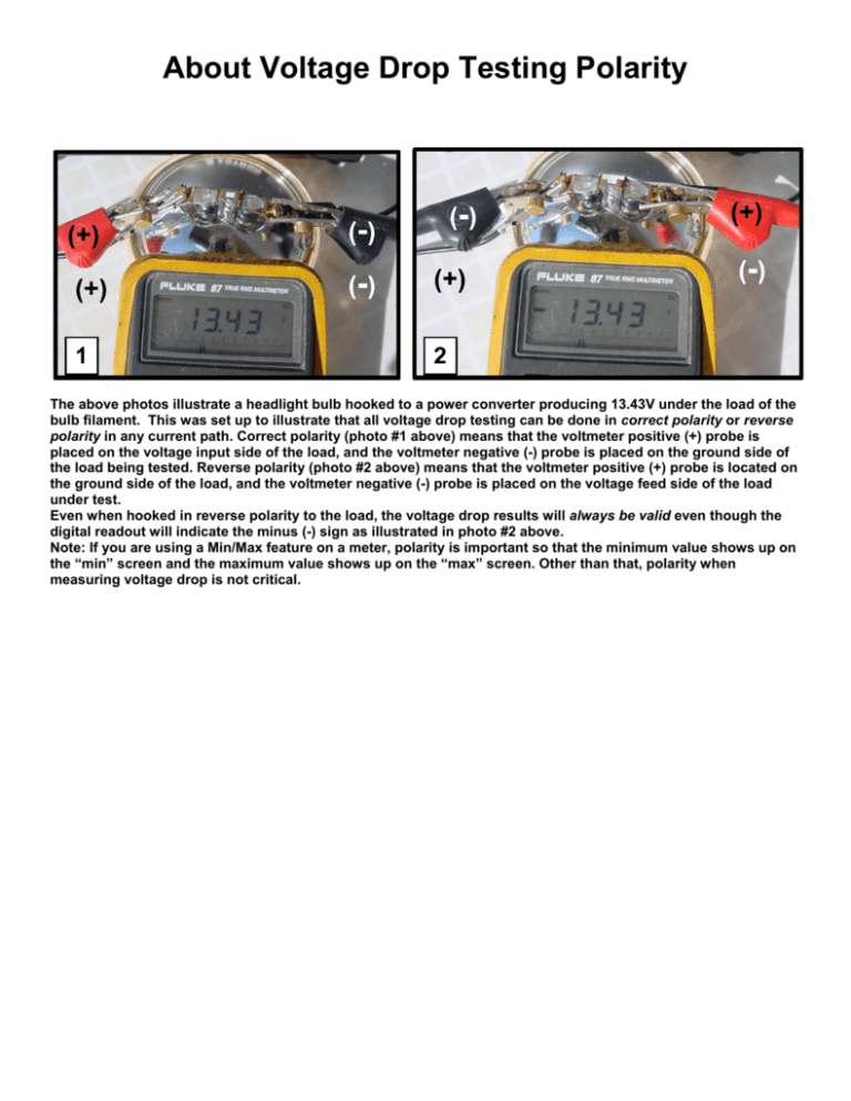
About Voltage Drop Testing Polarity The above photos illustrate a headlight bulb hooked to a power converter producing 13.43V under the load of the bulb filament. This was set up to illustrate that all voltage drop testing can be done in correct polarity or reverse polarity in any current path. Correct polarity (photo #1 above) means that the voltmeter positive (+) probe is placed on the voltage input side of the load, and the voltmeter negative (-) probe is placed on the ground side of the load being tested. Reverse polarity (photo #2 above) means that the voltmeter positive (+) probe is located on the ground side of the load, and the voltmeter negative (-) probe is placed on the voltage feed side of the load under test. Even when hooked in reverse polarity to the load, the voltage drop results will always be valid even though the digital readout will indicate the minus (-) sign as illustrated in photo #2 above. Note: If you are using a Min/Max feature on a meter, polarity is important so that the minimum value shows up on the “min” screen and the maximum value shows up on the “max” screen. Other than that, polarity when measuring voltage drop is not critical.
