transformer
advertisement

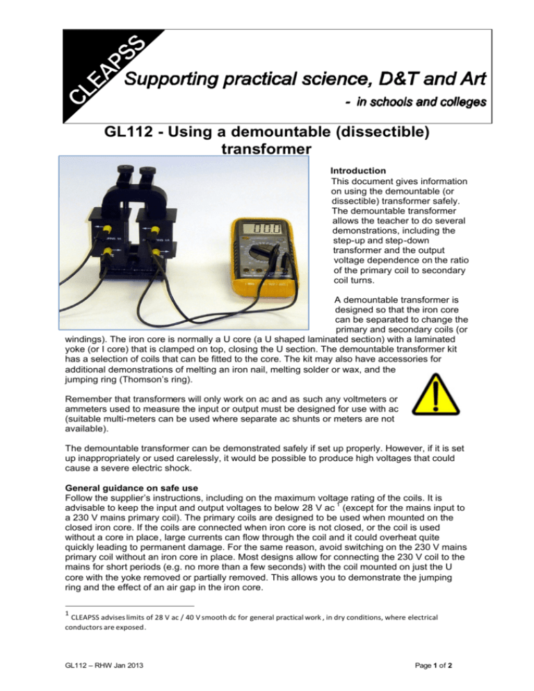
GL112 - Using a demountable (dissectible) transformer Introduction This document gives information on using the demountable (or dissectible) transformer safely. The demountable transformer allows the teacher to do several demonstrations, including the step-up and step-down transformer and the output voltage dependence on the ratio of the primary coil to secondary coil turns. A demountable transformer is designed so that the iron core can be separated to change the primary and secondary coils (or windings). The iron core is normally a U core (a U shaped laminated section) with a laminated yoke (or I core) that is clamped on top, closing the U section. The demountable transformer kit has a selection of coils that can be fitted to the core. The kit may also have accessories for additional demonstrations of melting an iron nail, melting solder or wax, and the jumping ring (Thomson’s ring). Remember that transformers will only work on ac and as such any voltmeters or ammeters used to measure the input or output must be designed for use with ac (suitable multi-meters can be used where separate ac shunts or meters are not available). The demountable transformer can be demonstrated safely if set up properly. However, if it is set up inappropriately or used carelessly, it would be possible to produce high voltages that could cause a severe electric shock. General guidance on safe use Follow the supplier’s instructions, including on the maximum voltage rating of the coils. It is advisable to keep the input and output voltages to below 28 V ac 1 (except for the mains input to a 230 V mains primary coil). The primary coils are designed to be used when mounted on the closed iron core. If the coils are connected when iron core is not closed, or the coil is used without a core in place, large currents can flow through the coil and it could overheat quite quickly leading to permanent damage. For the same reason, avoid switching on the 230 V mains primary coil without an iron core in place. Most designs allow for connecting the 230 V coil to the mains for short periods (e.g. no more than a few seconds) with the coil mounted on just the U core with the yoke removed or partially removed. This allows you to demonstrate the jumping ring and the effect of an air gap in the iron core. 1 CLEAPSS advises limits of 28 V ac / 40 V smooth dc for general practical work , in dry conditions, where electrical conductors are exposed. GL112 – RHW Jan 2013 Page 1 of 2 Step-up transformer or step-down transformer Use a low voltage input from an ac power pack on the primary coil and avoid coil combinations that would give a very high output voltage. Remember you can use the ratio of the number of turns on the primary coil to the number of turns on the secondary coils to calculate the output voltage and ensure that this is always less than 28 V ac. Do not use the mains coil as the secondary coil when demonstrating a step-up transformer. The large number of turns on the mains coil could produce a voltage significantly above 28 V ac – this would be extremely dangerous because the output current is not limited to 5 mA. Note that a very high voltage across the secondary coil is also likely to damage the coil insulation. Melting a nail When demonstrating the melting nail, use un-plated nails because the plating tends to flake off when heated and small blobs of hot metal can fly across the bench. If you squeeze the secondary coil ends together slightly before tightening the screws holding the nail, the nail will be under a small amount of tension, and will give a better demonstration because the nail separates cleanly when melting. The demonstrator and observers should wear eye protection because hot sparks can fly off. Put a heatproof mat below the nail to protect the bench. Jumping ring (Thomson’s ring) The yoke is mounted vertically above the primary mains coil and a solid copper or aluminium ring is placed over the core. When the alternating voltage is applied to the primary coil, the magnetic field from the induced current in the ring causes it to jump up. It can jump quite a height. Ensure that the current is switched on for a few moments only, just long enough to produce the effect as the current through the mains coil will be higher than normal because the core is open, with consequent increase in coil heating. Take care to avoid burns from the ring because it becomes very hot. Induction heating ring Use eye protection when melting solder or wax using the induction ring. Old or obsolete designs The mains coils supplied with older versions of this apparatus may not be manufactured to current safety standards. For example they have open windings or unsafe connectors for mains voltages, such as 4 mm sockets for ‘banana’ plugs, or spade connectors. The picture right shows an example of a transformer with unacceptable mains connectors. The mains coil should have a direct cord to the mains plug, or an IEC connector for power supply cords for mains voltages. The windings should be encapsulated or housed in such a way that you can’t touch them. If you have an old style mains coil which doesn’t meet this standard of safety, you should replace it with a modern design if available. If you are in any doubt about the safety of the apparatus in your school please contact CLEAPSS for advice. GL112 – RHW Jan 2013 Page 2 of 2


