Technical Publication
Hanger Spacing Guidelines
Cable Hanger Spacing
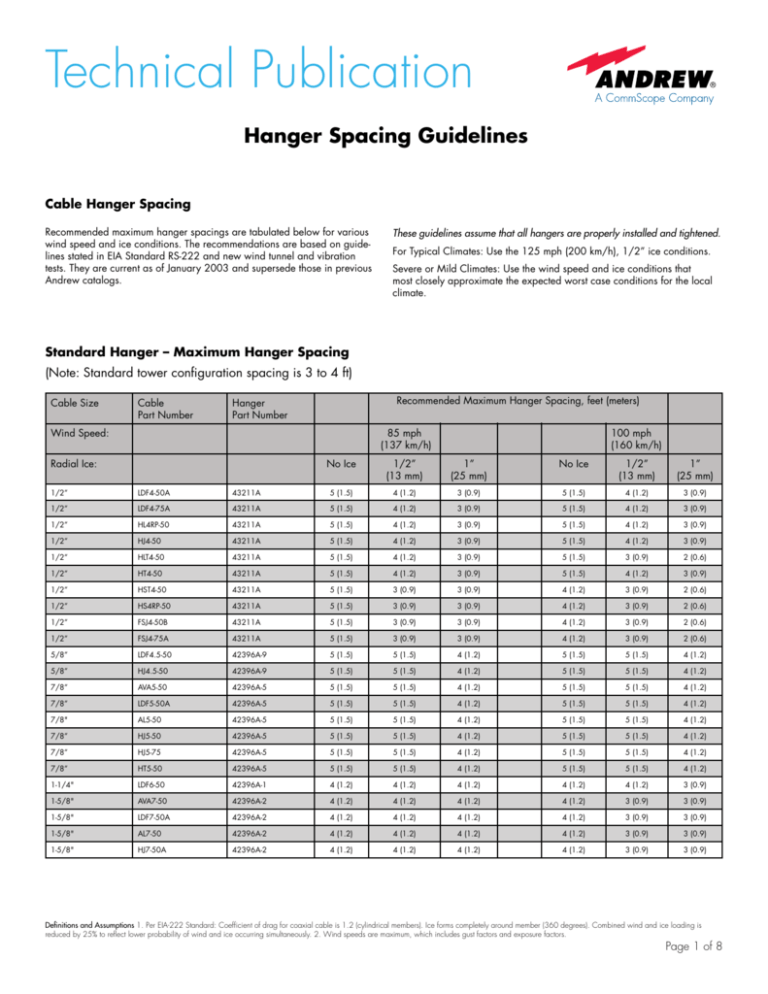
Recommended maximum hanger spacings are tabulated below for various
wind speed and ice conditions. The recommendations are based on guidelines stated in EIA Standard RS-222 and new wind tunnel and vibration
tests. They are current as of January 2003 and supersede those in previous
Andrew catalogs.
These guidelines assume that all hangers are properly installed and tightened.
For Typical Climates: Use the 125 mph (200 km/h), 1/2” ice conditions.
Severe or Mild Climates: Use the wind speed and ice conditions that
most closely approximate the expected worst case conditions for the local
climate.
Standard Hanger – Maximum Hanger Spacing
(Note: Standard tower configuration spacing is 3 to 4 ft)
Cable Size
Cable
Part Number
Recommended Maximum Hanger Spacing, feet (meters)
Hanger
Part Number
Wind Speed:
85 mph
(137 km/h)
Radial Ice:
No Ice
1/2”
(13 mm)
100 mph
(160 km/h)
1”
(25 mm)
No Ice
1/2”
(13 mm)
1”
(25 mm)
1/2”
LDF4-50A
43211A
5 (1.5)
4 (1.2)
3 (0.9)
5 (1.5)
4 (1.2)
3 (0.9)
1/2”
LDF4-75A
43211A
5 (1.5)
4 (1.2)
3 (0.9)
5 (1.5)
4 (1.2)
3 (0.9)
1/2”
HL4RP-50
43211A
5 (1.5)
4 (1.2)
3 (0.9)
5 (1.5)
4 (1.2)
3 (0.9)
1/2”
HJ4-50
43211A
5 (1.5)
4 (1.2)
3 (0.9)
5 (1.5)
4 (1.2)
3 (0.9)
1/2”
HLT4-50
43211A
5 (1.5)
4 (1.2)
3 (0.9)
5 (1.5)
3 (0.9)
2 (0.6)
1/2”
HT4-50
43211A
5 (1.5)
4 (1.2)
3 (0.9)
5 (1.5)
4 (1.2)
3 (0.9)
2 (0.6)
1/2”
HST4-50
43211A
5 (1.5)
3 (0.9)
3 (0.9)
4 (1.2)
3 (0.9)
1/2”
HS4RP-50
43211A
5 (1.5)
3 (0.9)
3 (0.9)
4 (1.2)
3 (0.9)
2 (0.6)
1/2”
FSJ4-50B
43211A
5 (1.5)
3 (0.9)
3 (0.9)
4 (1.2)
3 (0.9)
2 (0.6)
1/2”
FSJ4-75A
43211A
5 (1.5)
3 (0.9)
3 (0.9)
4 (1.2)
3 (0.9)
2 (0.6)
5/8”
LDF4.5-50
42396A-9
5 (1.5)
5 (1.5)
4 (1.2)
5 (1.5)
5 (1.5)
4 (1.2)
5/8”
HJ4.5-50
42396A-9
5 (1.5)
5 (1.5)
4 (1.2)
5 (1.5)
5 (1.5)
4 (1.2)
7/8”
AVA5-50
42396A-5
5 (1.5)
5 (1.5)
4 (1.2)
5 (1.5)
5 (1.5)
4 (1.2)
7/8”
LDF5-50A
42396A-5
5 (1.5)
5 (1.5)
4 (1.2)
5 (1.5)
5 (1.5)
4 (1.2)
4 (1.2)
7/8"
AL5-50
42396A-5
5 (1.5)
5 (1.5)
4 (1.2)
5 (1.5)
5 (1.5)
7/8”
HJ5-50
42396A-5
5 (1.5)
5 (1.5)
4 (1.2)
5 (1.5)
5 (1.5)
4 (1.2)
7/8”
HJ5-75
42396A-5
5 (1.5)
5 (1.5)
4 (1.2)
5 (1.5)
5 (1.5)
4 (1.2)
7/8”
HT5-50
42396A-5
5 (1.5)
5 (1.5)
4 (1.2)
5 (1.5)
5 (1.5)
4 (1.2)
1-1/4"
LDF6-50
42396A-1
4 (1.2)
4 (1.2)
4 (1.2)
4 (1.2)
4 (1.2)
3 (0.9)
1-5/8"
AVA7-50
42396A-2
4 (1.2)
4 (1.2)
4 (1.2)
4 (1.2)
3 (0.9)
3 (0.9)
1-5/8"
LDF7-50A
42396A-2
4 (1.2)
4 (1.2)
4 (1.2)
4 (1.2)
3 (0.9)
3 (0.9)
1-5/8"
AL7-50
42396A-2
4 (1.2)
4 (1.2)
4 (1.2)
4 (1.2)
3 (0.9)
3 (0.9)
1-5/8"
HJ7-50A
42396A-2
4 (1.2)
4 (1.2)
4 (1.2)
4 (1.2)
3 (0.9)
3 (0.9)
Definitions and Assumptions 1. Per EIA-222 Standard: Coefficient of drag for coaxial cable is 1.2 (cylindrical members). Ice forms completely around member (360 degrees). Combined wind and ice loading is
reduced by 25% to reflect lower probability of wind and ice occurring simultaneously. 2. Wind speeds are maximum, which includes gust factors and exposure factors.
Page 1 of 8
Technical Publication
Standard Hanger – Maximum Hanger Spacing
(Note: Standard tower configuration spacing is 3 to 4 ft)
Cable Size
Cable
Part Number
Recommended Maximum Hanger Spacing, feet (meters)
Hanger
Part Number
Wind Speed:
85 mph
(137 km/h)
Radial Ice:
No Ice
1/2”
(13 mm)
100 mph
(160 km/h)
1”
(25 mm)
No Ice
1/2”
(13 mm)
1”
(25 mm)
2-1/4”
LDF12-50A
42395A-4
4 (1.2)
4 (1.2)
4 (1.2)
4 (1.2)
3 (0.9)
3 (0.9)
2-1/4”
HJ12-50
42396A-4
4 (1.2)
4 (1.2)
4 (1.2)
4 (1.2)
3 (0.9)
3 (0.9)
3”
HJ8-50B
31766A-11
5 (1.5)
5 (1.5)
5 (1.5)
5 (1.5)
5 (1.5)
5 (1.5)
4”
HJ11-50B
31766A-10
5 (1.5)
5 (1.5)
5 (1.5)
5 (1.5)
5 (1.5)
5 (1.5)
5”
HJ9HP-50
33598-5
5 (1.5)
5 (1.5)
5 (1.5)
5 (1.5)
5 (1.5)
5 (1.5)
5”
HJ9-50
33598-5
5 (1.5)
5 (1.5)
5 (1.5)
5 (1.5)
5 (1.5)
5 (1.5)
Cable Size
Cable
Part Number
Hanger
Part Number
Recommended Maximum Hanger Spacing, feet (meters)
Wind Speed:
125 mph
(200 km/h)
Radial Ice:
150 mph
(240 km/h)
No Ice
1/2”
(13 mm)
1”
(25 mm)
No Ice
1/2”
(13 mm)
1”
(25 mm)
1/2”
LDF4-50A
43211A
4 (1.2)
3 (0.9)
2 (0.6)
3 (0.9)
2 (0.6)
1 (0.3)
1/2”
LDF4-75A
43211A
4 (1.2)
3 (0.9)
2 (0.6)
3 (0.9)
2 (0.6)
1 (0.3)
1/2”
HL4RP-50
43211A
4 (1.2)
3 (0.9)
2 (0.6)
3 (0.9)
2 (0.6)
1 (0.3)
1/2”
HJ4-50
43211A
4 (1.2)
3 (0.9)
2 (0.6)
3 (0.9)
2 (0.6)
1 (0.3)
1/2”
HLT4-50
43211A
4 (1.2)
3 (0.9)
2 (0.6)
3 (0.9)
2 (0.6)
1 (0.3)
1/2”
HT4-50
43211A
4 (1.2)
3 (0.9)
2 (0.6)
3 (0.9)
2 (0.6)
1 (0.3)
1/2”
HST4-50
43211A
3 (0.9)
3 (0.9)
2 (0.6)
3 (0.9)
2 (0.6)
1 (0.3)
1/2”
HS4RP-50
43211A
3 (0.9)
3 (0.9)
2 (0.6)
3 (0.9)
2 (0.6)
1 (0.3)
1/2”
FSJ4-50B
43211A
3 (0.9)
3 (0.9)
2 (0.6)
3 (0.9)
2 (0.6)
1 (0.3)
1/2”
FSJ4-75A
43211A
3 (0.9)
3 (0.9)
2 (0.6)
3 (0.9)
2 (0.6)
1 (0.3)
5/8”
LDF4.5-50
42396A-9
5 (1.5)
4 (1.2)
3 (0.9)
4 (1.2)
3 (0.9)
3 (0.9)
5/8”
HJ4.5-50
42396A-9
5 (1.5)
4 (1.2)
3 (0.9)
4 (1.2)
3 (0.9)
3 (0.9)
7/8”
AVA5-50
42396A-5
5 (1.5)
4 (1.2)
3 (0.9)
4 (1.2)
3 (0.9)
2 (0.6)
7/8”
LDF5-50A
42396A-5
5 (1.5)
4 (1.2)
3 (0.9)
4 (1.2)
3 (0.9)
2 (0.6)
7/8"
AL5-50
42396A-5
5 (1.5)
4 (1.2)
3 (0.9)
4 (1.2)
3 (0.9)
2 (0.6)
7/8”
HJ5-50
42396A-5
5 (1.5)
4 (1.2)
3 (0.9)
4 (1.2)
3 (0.9)
2 (0.6)
7/8”
HJ5-75
42396A-5
5 (1.5)
4 (1.2)
3 (0.9)
4 (1.2)
3 (0.9)
2 (0.6)
7/8”
HT5-50
42396A-5
5 (1.5)
4 (1.2)
3 (0.9)
4 (1.2)
3 (0.9)
2 (0.6)
1-1/4”
LDF6-50
42396A-1
4 (1.2)
4 (1.2)
3 (0.9)
3 (0.9)
3 (0.9)
3 (0.9)
1-5/8”
AVA7-50
42396A-2
3 (0.9)
3 (0.9)
3 (0.9)
3 (0.9)
3 (0.9)
2 (0.6)
1-5/8”
LDF7-50A
42396A-2
3 (0.9)
3 (0.9)
3 (0.9)
3 (0.9)
3 (0.9)
2 (0.6)
1-5/8"
AL7-50
42396A-2
3 (0.9)
3 (0.9)
3 (0.9)
3 (0.9)
3 (0.9)
2 (0.6)
1-5/8”
HJ7-50A
42396A-2
3 (0.9)
3 (0.9)
3 (0.9)
3 (0.9)
3 (0.9)
2 (0.6)
2-1/4”
LDF12-50
42395A-4
3 (0.9)
3 (0.9)
3 (0.9)
3 (0.9)
3 (0.9)
3 (0.9)
2-1/4”
HJ12-50
42396A-4
3 (0.9)
3 (0.9)
3 (0.9)
3 (0.9)
3 (0.9)
3 (0.9)
3”
HJ8-50B
31766A-11
5 (1.5)
5 (1.5)
5 (1.5)
5 (1.5)
5 (1.5)
5 (1.5)
4”
HJ11-50B
31766A-10
5 (1.5)
5 (1.5)
5 (1.5)
5 (1.5)
5 (1.5)
5 (1.5)
5”
HJ9HP-50
33598-5
5 (1.5)
5 (1.5)
5 (1.5)
5 (1.5)
5 (1.5)
5 (1.5)
5”
HJ9-50
33598-5
5 (1.5)
5 (1.5)
5 (1.5)
5 (1.5)
5 (1.5)
5 (1.5)
Definitions and Assumptions 1. Per EIA-222 Standard: Coefficient of drag for coaxial cable is 1.2 (cylindrical members). Ice forms completely around member (360 degrees). Combined wind and ice loading is
reduced by 25% to reflect lower probability of wind and ice occurring simultaneously. 2. Wind speeds are maximum, which includes gust factors and exposure factors.
Page 2 of 8
Technical Publication
Snap-In Hanger – Recommended Maximum Hanger Spacing
(Note: Standard tower configuration spacing is 3 to 4 ft)
Cable Size
Cable
Part Number
Recommended Maximum Hanger Spacing, feet (meters)
Hanger
Part Number
Wind Speed:
85 mph
(137 km/h)
Radial Ice:
100 mph
(160 km/h)
No Ice
1/2”
(13 mm)
1”
(25 mm)
No Ice
1/2”
(13 mm)
1”
(25 mm)
1/2”
LDF4-50A
SSH-12
4 (1.2)
4 (1.2)
3 (0.9)
4 (1.2)
3 (0.9)
2 (0.6)
1/2”
LDF4-75A
SSH-12
4 (1.2)
4 (1.2)
3 (0.9)
4 (1.2)
3 (0.9)
2 (0.6)
1/2”
HL4RP-50
SSH-12
4 (1.2)
4 (1.2)
3 (0.9)
4 (1.2)
3 (0.9)
2 (0.6)
1/2”
HJ4-50
SSH-12
4 (1.2)
4 (1.2)
3 (0.9)
4 (1.2)
3 (0.9)
2 (0.6)
1/2”
HLT4-50
SSH-12
4 (1.2)
4 (1.2)
3 (0.9)
4 (1.2)
3 (0.9)
2 (0.6)
1/2”
HT4-50
SSH-12
4 (1.2)
4 (1.2)
3 (0.9)
4 (1.2)
3 (0.9)
2 (0.6)
1/2”
HST4-50
SSH-12
4 (1.2)
4 (1.2)
3 (0.9)
4 (1.2)
3 (0.9)
2 (0.6)
1/2”
HS4RP-50
SSH-12
4 (1.2)
4 (1.2)
3 (0.9)
4 (1.2)
3 (0.9)
2 (0.6)
1/2”
FSJ4-50B
SSH-12
4 (1.2)
3 (0.9)
2 (0.6)
3 (0.9)
2 (0.6)
2 (0.6)
1/2”
FSJ4-75A
SSH-12
4 (1.2)
3 (0.9)
2 (0.6)
3 (0.9)
2 (0.6)
2 (0.6)
5/8”
LDF4.5-50
206706A-6
4 (1.2)
4 (1.2)
3 (0.9)
4 (1.2)
3 (0.9)
2 (0.6)
5/8”
HJ4.5-50
206706A-6
4 (1.2)
4 (1.2)
3 (0.9)
4 (1.2)
3 (0.9)
2 (0.6)
7/8”
AVA5-50
SSH-78
4 (1.2)
3 (0.9)
3 (0.9)
3 (0.9)
3 (0.9)
2 (0.6)
7/8”
LDF5-50A
SSH-78
4 (1.2)
3 (0.9)
3 (0.9)
3 (0.9)
3 (0.9)
2 (0.6)
7/8"
AL5-50
SSH-78
4 (1.2)
3 (0.9)
3 (0.9)
3 (0.9)
3 (0.9)
2 (0.6)
7/8”
HJ5-50
SSH-78
4 (1.2)
3 (0.9)
3 (0.9)
3 (0.9)
3 (0.9)
2 (0.6)
7/8”
HJ5-75
SSH-78
4 (1.2)
3 (0.9)
3 (0.9)
3 (0.9)
3 (0.9)
2 (0.6)
7/8”
HT5-50
SSH-78
4 (1.2)
3 (0.9)
3 (0.9)
3 (0.9)
3 (0.9)
2 (0.6)
1-1/4”
LDF6-50
SSH-114
3 (0.9)
3 (0.9)
3 (0.9)
3 (0.9)
3 (0.9)
2 (0.6)
1-5/8”
AVA7-50
SSH-158
3 (0.9)
3 (0.9)
3 (0.9)
3 (0.9)
3 (0.9)
2 (0.6)
1-5/8”
LDF7-50A
SSH-158
3 (0.9)
3 (0.9)
3 (0.9)
3 (0.9)
3 (0.9)
2 (0.6)
1-5/8"
AL7-50
SSH-158
3 (0.9)
3 (0.9)
3 (0.9)
3 (0.9)
3 (0.9)
2 (0.6)
1-5/8”
HJ7-50A
SSH-158
3 (0.9)
3 (0.9)
3 (0.9)
3 (0.9)
3 (0.9)
2 (0.6)
2-1/4”
LDF12-50
206706A-6
3 (0.9)
3 (0.9)
3 (0.9)
3 (0.9)
2 (0.6)
2 (0.6)
2-1/4”
HJ12-50
206706A-6
3 (0.9)
3 (0.9)
3 (0.9)
3 (0.9)
2 (0.6)
2 (0.6)
Definitions and Assumptions 1. Per EIA-222 Standard: Coefficient of drag for coaxial cable is 1.2 (cylindrical members). Ice forms completely around member (360 degrees). Combined wind and ice loading is
reduced by 25% to reflect lower probability of wind and ice occurring simultaneously. 2. Wind speeds are maximum, which includes gust factors and exposure factors.
Page 3 of 8
Technical Publication
Snap-In Hanger – Recommended Maximum Hanger Spacing
(Note: Standard tower configuration spacing is 3 to 4 ft)
Cable Size
Cable
Part Number
Recommended Maximum Hanger Spacing, feet (meters)
Hanger
Part Number
Wind Speed:
125 mph
(200 km/h)
Radial Ice:
150 mph
(240 km/h)
No Ice
1/2”
(13 mm)
1”
(25 mm)
No Ice
1/2”
(13 mm)
1”
(25 mm)
1/2”
LDF4-50A
SSH-12
3 (0.9)
3 (0.9)
2 (0.6)
3 (0.9)
2 (0.6)
1 (0.3)
1/2”
LDF4-75A
SSH-12
3 (0.9)
3 (0.9)
2 (0.6)
3 (0.9)
2 (0.6)
1 (0.3)
1/2”
HL4RP-50
SSH-12
3 (0.9)
3 (0.9)
2 (0.6)
3 (0.9)
2 (0.6)
1 (0.3)
1/2”
HJ4-50
SSH-12
3 (0.9)
3 (0.9)
2 (0.6)
3 (0.9)
2 (0.6)
1 (0.3)
1/2”
HLT4-50
SSH-12
3 (0.9)
3 (0.9)
2 (0.6)
3 (0.9)
2 (0.6)
1 (0.3)
1/2”
HT4-50
SSH-12
3 (0.9)
3 (0.9)
2 (0.6)
3 (0.9)
2 (0.6)
1 (0.3)
1/2”
HST4-50
SSH-12
3 (0.9)
3 (0.9)
2 (0.6)
3 (0.9)
2 (0.6)
1 (0.3)
1/2”
HS4RP-50
SSH-12
3 (0.9)
3 (0.9)
2 (0.6)
3 (0.9)
2 (0.6)
1 (0.3)
1/2”
FSJ4-50B
SSH-12
3 (0.9)
2 (0.6)
1 (0.3)
2 (0.6)
2 (0.6)
1 (0.3)
1/2”
FSJ4-75A
SSH-12
3 (0.9)
2 (0.6)
1 (0.3)
2 (0.6)
2 (0.6)
1 (0.3)
5/8”
LDF4.5-50
206706A-6
3 (0.9)
3 (0.9)
2 (0.6)
2 (0.6)
2 (0.6)
1 (0.3)
5/8”
HJ4.5-50
206706A-6
3 (0.9)
3 (0.9)
2 (0.6)
2 (0.6)
2 (0.6)
1 (0.3)
7/8”
AVA5-50
SSH-78
3 (0.9)
3 (0.9)
2 (0.6)
2 (0.6)
1 (0.3)
1 (0.3)
7/8”
LDF5-50A
SSH-78
3 (0.9)
3 (0.9)
2 (0.6)
2 (0.6)
1 (0.3)
1 (0.3)
7/8"
AL5-50
SSH-78
3 (0.9)
3 (0.9)
2 (0.6)
2 (0.6)
1 (0.3)
1 (0.3)
7/8”
HJ5-50
SSH-78
3 (0.9)
3 (0.9)
2 (0.6)
2 (0.6)
1 (0.3)
1 (0.3)
7/8”
HJ5-75
SSH-78
3 (0.9)
3 (0.9)
2 (0.6)
2 (0.6)
1 (0.3)
1 (0.3)
7/8”
HT5-50
SSH-78
3 (0.9)
3 (0.9)
2 (0.6)
2 (0.6)
1 (0.3)
1 (0.3)
1-1/4”
LDF6-50
SSH-114
3 (0.9)
3 (0.9)
2 (0.6)
2 (0.6)
1 (0.3)
1 (0.3)
1-5/8”
AVA7-50
SSH-158
3 (0.9)
3 (0.9)
2 (0.6)
2 (0.6)
1 (0.3)
1 (0.3)
1-5/8”
LDF7-50A
SSH-158
3 (0.9)
3 (0.9)
2 (0.6)
2 (0.6)
1 (0.3)
1 (0.3)
1-5/8"
AL7-50
SSH-158
3 (0.9)
3 (0.9)
2 (0.6)
2 (0.6)
1 (0.3)
1 (0.3)
1-5/8”
HJ7-50A
SSH-158
3 (0.9)
3 (0.9)
2 (0.6)
2 (0.6)
1 (0.3)
1 (0.3)
2-1/4”
LDF12-50
206706A-6
3 (0.9)
3 (0.9)
2 (0.6)
2 (0.6)
1 (0.3)
1 (0.3)
2-1/4”
HJ12-50
206706A-6
2 (0.6)
2 (0.6)
1 (0.3)
2 (0.6)
1 (0.3)
1 (0.3)
Definitions and Assumptions 1. Per EIA-222 Standard: Coefficient of drag for coaxial cable is 1.2 (cylindrical members). Ice forms completely around member (360 degrees). Combined wind and ice loading is
reduced by 25% to reflect lower probability of wind and ice occurring simultaneously. 2. Wind speeds are maximum, which includes gust factors and exposure factors.
Page 4 of 8
Technical Publication
Click-On Hanger – Recommended Maximum Hanger Spacing
(Note: Standard tower configuration spacing is 3 to 4 ft)
Cable Size
Cable
Part Number
Recommended Maximum Hanger Spacing, feet (meters)
Hanger
Part Number
Wind Speed:
85 mph
(137 km/h)
Radial Ice:
100 mph
(160 km/h)
No Ice
1/2”
(13 mm)
1”
(25 mm)
No Ice
1/2”
(13 mm)
1”
(25 mm)
1/2”
LDF4-50A
L4CLICK, 1 Stack
3 (0.9)
3 (0.9)
3 (0.9)
3 (0.9)
3 (0.9)
3 (0.9)
1/2”
LDF4-50A
L4CLICK, 2 Stack
3 (0.9)
3 (0.9)
3 (0.9)
3 (0.9)
3 (0.9)
3 (0.9)
1/2”
LDF4-50A
L4CLICK, 3 Stack
3 (0.9)
3 (0.9)
3 (0.9)
3 (0.9)
3 (0.9)
3 (0.9)
Note: These same hanger spacing recommendations apply for the other following 1/2” cable types: LDF4-75A, HL4RP-50, HLT4-50, HS4RP-50, HST4-50, HT4-50, HJ4-50
5/8”
LDF4.5-50A
L45CLICK, 1 Stack
3 (0.9)
3 (0.9)
3 (0.9)
3 (0.9)
3 (0.9)
3 (0.9)
5/8”
LDF4.5-50A
L45CLICK, 2 Stack
3 (0.9)
3 (0.9)
3 (0.9)
3 (0.9)
3 (0.9)
3 (0.9)
5/8”
LDF4.5-50A
L45CLICK, 3 Stack
3 (0.9)
3 (0.9)
3 (0.9)
3 (0.9)
3 (0.9)
3 (0.9)
Note: These same hanger spacing recommendations apply for the other following 5/8” cable types: HJ4.5-50
7/8”
LDF5-50A
L5CLICK, 1 Stack
4 (1.2)
4 (1.2)
4 (1.2)
3 (0.9)
3 (0.9)
3 (0.9)
7/8”
LDF5-50A
L5CLICK, 2 Stack
4 (1.2)
4 (1.2)
4 (1.2)
3 (0.9)
3 (0.9)
3 (0.9)
7/8”
LDF5-50A
L5CLICK, 3 Stack
4 (1.2)
4 (1.2)
4 (1.2)
3 (0.9)
3 (0.9)
3 (0.9)
Note: These same hanger spacing recommendations apply for the other following 7/8” cable types: AVA5-50, VXL5-50, AL5-50, HJ5-50, HJ5-75, HT5-5
1-1/4”
LDF6-50
L6CLICK, 1 Stack
4 (1.2)
4 (1.2)
4 (1.2)
3 (0.9)
3 (0.9)
3 (0.9)
1-1/4”
LDF6-50
L6CLICK, 2 Stack
4 (1.2)
4 (1.2)
4 (1.2)
3 (0.9)
3 (0.9)
3 (0.9)
1-1/4”
LDF6-50
L6CLICK, 3 Stack
3 (0.9)
3 (0.9)
3 (0.9)
3 (0.9)
3 (0.9)
3 (0.9)
1-5/8”
LDF7-50A
L7CLICK, 1 Stack
4 (1.2)
4 (1.2)
4 (1.2)
3 (0.9)
3 (0.9)
3 (0.9)
1-5/8”
LDF7-50A
L7CLICK, 2 Stack
3 (0.9)
3 (0.9)
3 (0.9)
3 (0.9)
3 (0.9)
3 (0.9)
1-5/8”
LDF7-50A
L7CLICK, 3 Stack
3 (0.9)
3 (0.9)
3 (0.9)
3 (0.9)
3 (0.9)
3 (0.9)
Note: These same hanger spacing recommendations apply for the other following 1 5/8” cable types: HJ7-50A, AVA7-50, AL7-50
* These hanger spacings have been specified based on using the Click-On Hangers with Andrew specified hardware kits.
Definitions and Assumptions 1. Per EIA-222 Standard: Coefficient of drag for coaxial cable is 1.2 (cylindrical members). Ice forms completely around member (360 degrees). Combined wind and ice loading is
reduced by 25% to reflect lower probability of wind and ice occurring simultaneously. 2. Wind speeds are maximum, which includes gust factors and exposure factors.
Page 5 of 8
Technical Publication
Click-On Hanger – Recommended Maximum Hanger Spacing
(Note: Standard tower configuration spacing is 3 to 4 ft)
Cable Size
Cable
Part Number
Recommended Maximum Hanger Spacing, feet (meters)
Hanger
Part Number
Wind Speed:
125 mph
(200 km/h)
Radial Ice:
150 mph
(240 km/h)
No Ice
1/2”
(13 mm)
1”
(25 mm)
No Ice
1/2”
(13 mm)
1”
(25 mm)
1/2”
LDF4-50A
L4CLICK, 1 Stack
3 (0.9)
3 (0.9)
3 (0.9)
2 (0.6)
2 (0.6)
2 (0.6)
1/2”
LDF4-50A
L4CLICK, 2 Stack
3 (0.9)
3 (0.9)
3 (0.9)
2 (0.6)
2 (0.6)
2 (0.6)
1/2”
LDF4-50A
L4CLICK, 3 Stack
3 (0.9)
3 (0.9)
3 (0.9)
2 (0.6)
2 (0.6)
2 (0.6)
Note: These same hanger spacing recommendations apply for the other following 1/2” cable types: LDF4-75A, HL4RP-50, HLT4-50, HS4RP-50, HST4-50, HT4-50, HJ4-50
5/8”
LDF4.5-50A
L45CLICK, 1 Stack
3 (0.9)
3 (0.9)
3 (0.9)
2 (0.6)
2 (0.6)
2 (0.6)
5/8”
LDF4.5-50A
L45CLICK, 2 Stack
3 (0.9)
3 (0.9)
3 (0.9)
2 (0.6)
2 (0.6)
2 (0.6)
5/8”
LDF4.5-50A
L45CLICK, 3 Stack
2 (0.6)
2 (0.6)
2 (0.6)
2 (0.6)
2 (0.6)
2 (0.6)
Note: These same hanger spacing recommendations apply for the other following 5/8” cable types: HJ4.5-50
7/8”
LDF5-50A
L5CLICK, 1 Stack
3 (0.9)
3 (0.9)
3 (0.9)
2 (0.6)
2 (0.6)
2 (0.6)
7/8”
LDF5-50A
L5CLICK, 2 Stack
3 (0.9)
3 (0.9)
3 (0.9)
2 (0.6)
2 (0.6)
2 (0.6)
7/8”
LDF5-50A
L5CLICK, 3 Stack
2 (0.6)
2 (0.6)
2 (0.6)
2 (0.6)
2 (0.6)
2 (0.6)
Note: These same hanger spacing recommendations apply for the other following 7/8” cable types: AVA5-50, VXL5-50, AL5-50, HJ5-50, HJ5-75, HT5-5
1-1/4”
LDF6-50
L6CLICK, 1 Stack
3 (0.9)
3 (0.9)
3 (0.9)
2 (0.6)
2 (0.6)
2 (0.6)
1-1/4”
LDF6-50
L6CLICK, 2 Stack
3 (0.9)
3 (0.9)
3 (0.9)
2 (0.6)
2 (0.6)
2 (0.6)
1-1/4”
LDF6-50
L6CLICK, 3 Stack
2 (0.6)
2 (0.6)
2 (0.6)
2 (0.6)
2 (0.6)
2 (0.6)
1-5/8”
LDF7-50A
L7CLICK, 1 Stack
3 (0.9)
3 (0.9)
3 (0.9)
2 (0.6)
2 (0.6)
2 (0.6)
1-5/8”
LDF7-50A
L7CLICK, 2 Stack
2 (0.6)
2 (0.6)
2 (0.6)
2 (0.6)
2 (0.6)
2 (0.6)
1-5/8”
LDF7-50A
L7CLICK, 3 Stack
2 (0.6)
2 (0.6)
2 (0.6)
2 (0.6)
2 (0.6)
2 (0.6)
Note: These same hanger spacing recommendations apply for the other following 1 5/8” cable types: HJ7-50A, AVA7-50, AL7-50
Mini Click-On Hanger – Recommended Maximum Hanger Spacing
(Note: Standard tower configuration spacing is 3 to 4 ft)
Cable Size
Cable
Part Number
Hanger
Part Number
Recommended Maximum Hanger Spacing, feet (meters)
Wind Speed:
125 mph
(200 km/h)
Radial Ice:
No Ice
1/2”
(13 mm)
1”
(25 mm)
6 mm - 8mm
CNT-240, CNT-300, FSJ1 series
68MCLICK, 1 Stack
1.5 (0.61)
1.5 (0.61)
1.5 (0.61)
6 mm - 8mm
CNT-240, CNT-300, FSJ1 series
68MCLICK, 2 Stack
1.5 (0.61)
1.5 (0.61)
1.5 (0.61)
6 mm - 8mm
CNT-240, CNT-300, FSJ1 series
68MCLICK, 3 Stack
1.5 (0.61)
1.5 (0.61)
1.5 (0.61)
9 mm - 12 mm
CNT-400, LDF1, FSJ2, LDF2, EFX2 series
912MCLICK, 1 Stack
3 (0.9)
3 (0.9)
3 (0.9)
9 mm - 12 mm
CNT-400, LDF1, FSJ2, LDF2, EFX2 series
912MCLICK, 2 Stack
3 (0.9)
3 (0.9)
3 (0.9)
9 mm - 12 mm
CNT-400, LDF1, FSJ2, LDF2, EFX2 series
912MCLICK, 3 Stack
2 (0.6)
2 (0.6)
2 (0.6)
13 mm - 16 mm
CNT-500, CNT-600, FSJ and LDF4 series
1316MCLICK, 1 Stack
3 (0.9)
3 (0.9)
3 (0.9)
13 mm - 16 mm
CNT-500, CNT-600, FSJ and LDF4 series
1316MCLICK, 2 Stack
3 (0.9)
3 (0.9)
3 (0.9)
13 mm - 16 mm
CNT-500, CNT-600, FSJ and LDF4 series
1316MCLICK, 3 Stack
2 (0.6)
2 (0.6)
2 (0.6)
* These hanger spacings have been specified based on using the Click-On Hangers with Andrew specified hardware kits.
Definitions and Assumptions 1. Per EIA-222 Standard: Coefficient of drag for coaxial cable is 1.2 (cylindrical members). Ice forms completely around member (360 degrees). Combined wind and ice loading is
reduced by 25% to reflect lower probability of wind and ice occurring simultaneously. 2. Wind speeds are maximum, which includes gust factors and exposure factors.
Page 6 of 8
Technical Publication
Hanger Spacing for HELIAX® Elliptical Waveguide
Recommended maximum hanger spacings are tabulated below for various wind
speed and ice conditions. The recommendations are based on guidelines stated
in EIA Standard RS-222 and new wind tunnel and vibration tests. They supersede
those in previous Andrew catalogs.
Installations in Typical Climates. Use the 125 mph (200 km/h),
1/2” ice conditions.
Severe or Mild Climates. Use the wind speed and ice conditions that
most closely approximate the expected worst case conditions for the
local climate.
Standard Hanger for HELIAX® Elliptical Waveguide – Recommended Maximum Hanger Spacing
(Note: Standard tower configuration spacing is 3 to 4 ft)
Waveguide
Type
Recommended Maximum Hanger Spacing, feet (meters)
Hanger
Type Number
Wind Speed:
85 mph
(137 km/h)
Radial Ice:
100 mph
(160 km/h)
No Ice
1/2”
(13 mm)
1”
(25 mm)
No Ice
1/2”
(13 mm)
1”
(25 mm)
6 (1.8)
EW17, EWP17
31766A-9
6 (1.8)
6 (1.8)
6 (1.8)
6 (1.8)
6 (1.8)
EW20
31766A-10
6 (1.8)
6 (1.8)
6 (1.8)
6 (1.8)
6 (1.8)
6 (1.8)
EW28
31766A-11
6 (1.8)
6 (1.8)
6 (1.8)
6 (1.8)
6 (1.8)
5.5 (1.68)
EW34, EWP34
42396A-15
6 (1.8)
6 (1.8)
6 (1.8)
6 (1.8)
5.5 (1.68)
6 (1.8)
EW37, EWP37
42396A-4
6 (1.8)
6 (1.8)
5.5 (1.68)
5.5 (1.68)
5.5 (1.68)
5 (1.5)
EW43, EWP43
42396A-16
6 (1.8)
6 (1.8)
5.5 (1.68)
5 (1.5)
5 (1.5)
4.5 (1.37)
EW52, EWP52
42396A-8
5.5 (1.68)
5 (1.5)
4.5 (1.37)
4.5 (1.37)
4.5 (1.37)
4 (1.2)
EW63, EWP63
42396A-7
5 (1.5)
4.5 (1.37)
4 (1.2)
4 (1.2)
4 (1.2)
3.5 (1.07)
EW64, EWP64
42396A-1
5 (1.5)
6 (1.8)
4 (1.2)
4.5 (1.37)
4 (1.2)
3.5 (1.07)
EW77, EWP77
42396A-11
5 (1.5)
6 (1.8)
4 (1.2)
4.5 (1.37)
4 (1.2)
3.5 (1.07)
EW85
42396A-5
5.5 (1.68)
6 (1.8)
4 (1.2)
4.5 (1.37)
4 (1.2)
3.5 (1.07)
EW90, EWP90
42396A-5
5.5 (1.68)
4.5 (1.37)
4 (1.2)
4.5 (1.37)
4 (1.2)
3 (0.9)
EW127A, EWP127A
42396A-9
5.5 (1.68)
4.5 (1.37)
3.5 (1.07)
4.5 (1.37)
4 (1.2)
3 (0.9)
EW132, EWP132
42396A-9
5.5 (1.68)
4.5 (1.37)
3.5 (1.07)
5 (1.2)
4 (1.2)
3 (0.9)
EW180, EWP180
43211A
6 (1.8)
4.5 (1.37)
3.5 (1.07)
5 (1.2)
4 (1.2)
3 (0.9)
EW220
43211A
6 (1.8)
4.5 (1.37)
3.5 (1.07)
5 (1.2)
4 (1.2)
3 (0.9)
EW240
43211A
6 (1.8)
4.5 (1.37)
3.5 (1.07)
5 (1.2)
4 (1.2)
3 (0.9)
Definitions and Assumptions 1. Per EIA-222 Standard: Coefficient of drag for elliptical waveguide is 1.6 (average of 1.2 for cylindrical and 2.0 for flat members). Ice forms completely around member (360 degrees).
Combined wind and ice loading is reduced by 25% to reflect lower probability of wind and ice occurring simultaneously. 2. Wind speeds are maximum, which includes gust factors and exposure factors.
Page 7 of 8
Technical Publication
Standard Hanger for HELIAX® Elliptical Waveguide – Recommended Maximum Hanger Spacing
(Note: Standard tower configuration spacing is 3 to 4 ft)
Waveguide
Type
Recommended Maximum Hanger Spacing, feet (meters)
Hanger
Type Number
Wind Speed:
125 mph
(200 km/h)
Radial Ice:
No Ice
150 mph
(240 km/h)
1/2”
(13 mm)
1”
(25 mm)
No Ice
1/2”
(13 mm)
1”
(25 mm)
4.5 (1.37)
EW17, EWP17
31766A-9
6 (1.8)
6 (1.8)
5.5 (1.68)
5 (1.5)
5 (1.5)
EW20
31766A-10
5.5 (1.68)
5.5 (1.68)
5 (1.5)
4.5 (1.37)
4.5 (1.37)
4 (1.2)
EW28
31766A-11
5 (1.5)
5 (1.5)
4.5 (1.37)
4 (1.2)
4 (1.2)
3.5 (1.07)
EW34, EWP34
42396A-15
4.5 (1.37)
4.5 (1.37)
4 (1.2)
4 (1.2)
3.5 (1.07)
4 (1.2)
EW37, EWP37
42396A-4
4.5 (1.37)
4.5 (1.37)
4 (1.2)
3.5 (1.07)
3.5 (1.07)
3 (.09)
EW43, EWP43
42396A-16
4 (1.2)
4 (1.2)
3.5 (1.07)
3.5 (1.07)
3.5 (1.07)
3 (.09)
EW52, EWP52
42396A-8
3.5 (1.07)
3.5 (1.07)
3 (.09)
3 (.09)
3 (.09)
2.5 (0.76)
EW63, EWP63
42396A-7
3.5 (1.07)
3 (0.9)
2.5 (0.76)
2.5 (0.76)
2.5 (0.76)
2 (0.6)
EW64, EWP64
42396A-1
3.5 (1.07)
3 (0.9)
2.5 (0.76)
3 (.09)
2.5 (0.76)
2 (0.6)
EW77, EWP77
42396A-11
3.5 (1.07)
3 (0.9)
2.5 (0.76)
3 (.09)
2.5 (0.76)
2 (0.6)
EW85
42396A-5
3.5 (1.07)
3 (0.9)
2.5 (0.76)
3 (.09)
2.5 (0.76)
2 (0.6)
EW90, EWP90
42396A-5
3.5 (1.07)
3 (0.9)
2.5 (0.76)
3 (.09)
2.5 (0.76)
2 (0.6)
EW127A, EWP127A
42396A-9
3.5 (1.07)
3 (0.9)
2.5 (0.76)
3 (.09)
2.5 (0.76)
2 (0.6)
EW132, EWP132
42396A-9
4 (1.2)
3 (0.9)
2.5 (0.76)
3 (.09)
2.5 (0.76)
2 (0.6)
EW180, EWP180
43211A
4 (1.2)
3 (0.9)
2.5 (0.76)
3.5 (1.07)
2.5 (0.76)
2 (0.6)
EW220
43211A
4 (1.2)
3 (0.9)
2.5 (0.76)
3.5 (1.07)
2.5 (0.76)
2 (0.6)
EW240
43211A
4 (1.2)
3 (0.9)
2.5 (0.76)
3.5 (1.07)
2.5 (0.76)
2 (0.6)
Definitions and Assumptions 1. Per EIA-222 Standard: Coefficient of drag for elliptical waveguide is 1.6 (average of 1.2 for cylindrical and 2.0 for flat members). Ice forms completely around member (360 degrees).
Combined wind and ice loading is reduced by 25% to reflect lower probability of wind and ice occurring simultaneously. 2. Wind speeds are maximum, which includes gust factors and exposure factors.
www.commscope.com/andrew
Visit our Web site or contact your local Andrew Solutions representative for more information.
© 2009 CommScope, Inc. All rights reserved.
Andrew Solutions is a trademark of CommScope. All trademarks identified by ® or ™ are registered trademarks or trademarks, respectively, of CommScope.
This document is for planning purposes only and is not intended to modify or supplement any specifications or warranties relating to Andrew Solutions products or services.
TP-101619.2-EN (8/09)
Page 8 of 8

