QO®, QOM2 and Q-Frame Enclosed Circuit Breakers—Class 1131
General Information and Application Data
GENERAL INFORMATION AND APPLICATION DATA
Type
Enclosed molded case circuit breakers are UL® Listed; File E136861, for
enclosures and File E10027 for circuit breakers.
Molded case circuit breakers meet Federal Specifications W-C-375-B.
Enclosed molded case switches are UL Listed under File E59921.
Service
120/240 Vac, 1φ3W
240 Vac, 1φ2W
240 Vac, 1φ3W
240/120 Vac, 3φ4W
208Y/120 Vac, 3φ4W
Ratings
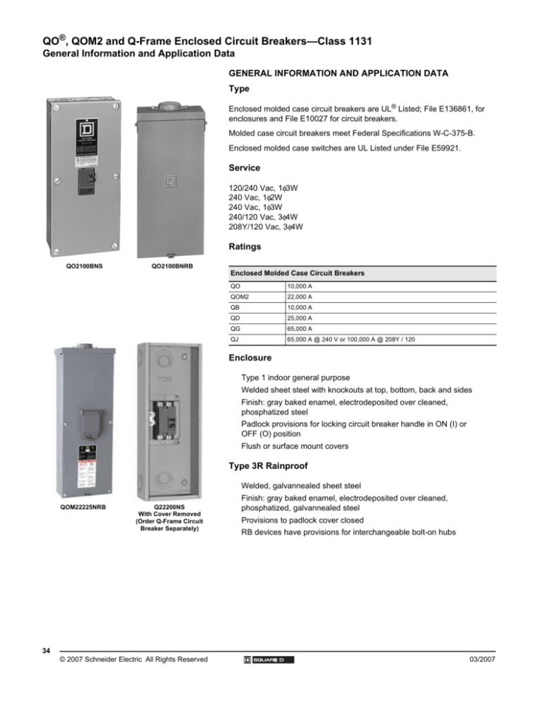
QO2100BNS
QO2100BNRB
Enclosed Molded Case Circuit Breakers
QO
10,000 A
QOM2
22,000 A
QB
10,000 A
QD
25,000 A
QG
65,000 A
QJ
65,000 A @ 240 V or 100,000 A @ 208Y / 120
Enclosure
Type 1 indoor general purpose
Welded sheet steel with knockouts at top, bottom, back and sides
Finish: gray baked enamel, electrodeposited over cleaned,
phosphatized steel
Padlock provisions for locking circuit breaker handle in ON (I) or
OFF (O) position
Flush or surface mount covers
Type 3R Rainproof
Welded, galvannealed sheet steel
QOM22225NRB
34
Q22200NS
With Cover Removed
(Order Q-Frame Circuit
Breaker Separately)
© 2007 Schneider Electric All Rights Reserved
Finish: gray baked enamel, electrodeposited over cleaned,
phosphatized, galvannealed steel
Provisions to padlock cover closed
RB devices have provisions for interchangeable bolt-on hubs
03/2007
QO®, QOM2 and Q-Frame Enclosed Circuit Breakers—Class 1131
Technical Information
TECHNICAL INFORMATION
Enclosed Molded-Case Circuit Breaker Ratings
Circuit Breaker 1
Enclosure
Service
Rating in
Amperes
Type 1
Catalog
Number
Enclosure
UL® Listed
No.
Catalog Interrupting Rating
(Page 37) Number
in RMS Amps
Symmetrical
Type 3R
Catalog
Number
Neutral Assembly
Terminal Wire Size
AWG/kcmil
Terminal
Lug Wire
Neutral
Size
AWG/kcmil Terminals
Grounding
Terminals
Enclosed Circuit Breaker Mounting Base
G
B
60 A 2
QO2TR 3
1R
QO210 to
QO260
#14 4
Al or Cu 4
10,000 AIR
#14 8
Al or Cu
240 Vac
Enclosed Circuit Breakers
100 A
S
N
125 A
QO2100BNF/S 5
QO2125BNF/S 5
QO2100BNRB 5
QO2125BNRB 5
QO
QO-PL
QO-GFI
10,000 AIR
QO-VH
22,000 AIR
QO
QO-PL
QO-GFI
10,000 AIR
QO-VH
22,000 AIR
6, 6R
QOM2-VH
22,000 AIR
10,000 AIR
1, 2R
QO
QO-PL
QO-GFI
QO-VH
22,000 AIR
QBL
QDL
QGL
QJL
10,000 AIR
25,000 AIR
65,000 AIR
100,000 AIR
QBL
QDL
QGL
QJL
10,000 AIR
25,000 AIR
65,000 AIR
100,000 AIR9
1, 2R
2, 3R
120/240 Vac
100-225 A
S
N
100 A
QOM22225NF/S
6
QO3100BNF/S 5
QOM22225NRB
6
QO3100BNRB 5
240 Vac
S
N
2-pole
240 Vac Max.
S
N
Q22200NS 7 8
Q22200NRB 7 8
3, 4R
100-225 A
100-225 A
Q23225NF/S
8
Q23225NF/S
8
Q23225NRB
8
Q23225NRB
8
4, 5R
4, 5R
3-pole
240 Vac
#12 1 Al
or
#14 1 Cu
#12 1 Al
or
#14 1 Cu
#12 2/ 0 Al
#14 2/0 Cu
#12 2/0 Al
#14 2 /0 Cu
4 - #4 2 50
kcmil Al/Cu
1
Order circuit breaker separately.
2
Not suitable for service equipment.
3
Top endwall has no hub opening; back and bottom feed only.
4
Load terminals use #6 maximum.
5
Enclosures will accept QO circuit breakers with factory-installed accessories.
6
Enclosure will accept QOM2 circuit breaker with factory-installed accessories.
7
Accepts 200 A maximum, 2-pole Q-frame circuit breakers.
8
Equipment grounding kit factory-installed.
9
When these 3-pole circuit breakers are mounted in an enclosure, the maximum AIR rating is 65,000 at 240 Vac and 100,000 at 208 Vac.
36
© 2007 Schneider Electric All Rights Reserved
#12 1 Al
or
#14 1 Cu
2 - #4 25 0
kcmil
4 - #14 2/ 0
Al or Cu
#12 1 Al
or
#14 1 Cu
#12 2 Al
or
#14 2 Cu
2 - #6 2 /0 Al
2 - #10 2/0 Cu
#12 2 Al
or
#14 2 Cu
#4 2 50
Al or Cu
#4 300
Al or Cu
#4 3 00
Al or Cu
#12 1/ 0 Al
or
#14 1/0 Cu
#4 3 00
Al or Cu
03/2007
QO®, QOM2 and Q-Frame Enclosed Circuit Breakers—Class 1131
Dimensions and Knockouts
DIMENSIONS AND KNOCKOUTS
Dimensions
W
Enclosure No.
H
D
in.
mm
in.
mm
in.
mm
1
5.88
149
13.12
333
3.38
86
2
5.88
149
16.12
409
3.38
86
1R
4.56
116
6.50
165
3.88
99
2R
6.92
176
13.12
333
4.12
105
3R
6.92
176
16.12
409
4.12
105
3
7.56
192
23.12
587
4.25
108
4
9.62
244
26.12
663
4.75
121
4R
7.56
192
23.24
590
4.75
121
5R
9.62
244
26.24
666
5.50
140
6
8.55
217
23.92
608
3.95
100
6R
8.55
217
24.75
629
4.16
106
Knockouts
A
Symbol
Conduit Size
B
C
D
E
F
0.50 in.
0.75 in.
1.00 in.
1.25 in.
1.50 in.
2.00 in.
G
2.50 in.
H
3.00 in.
13 mm
19 mm
25 mm
32 mm
38 mm
51 mm
64 mm
76 mm
D, E, F, G
2-1/2 in.
Hub Max.
C,D,E,F
A,B,C,D
A,B
C,D,E,F
A,B,C
Box 1R
Box 1, 2
E,F,G,H
C,D,E,F
D,E,F,G
B,C,D,E
Box 2R, 3R
Box 3
2-1/2 in.
Hub Max.
2-1/2 in.
Hub Max.
A,B,C,D
2-1/2 in.
Hub Max.
C,D,E,F
A,B
A,B
D,E,F,G
Box 4
A,B
D,E,F,G
E,F,G,H
Box 4R
C,D,E,F
C,D,E,F
C,D,E,F
Box 5R
Box 6
Box 6R
Outdoor Dimensions and Knockouts
03/2007
© 2007 Schneider Electric All Rights Reserved
37


