2D nM 1E 6W
advertisement
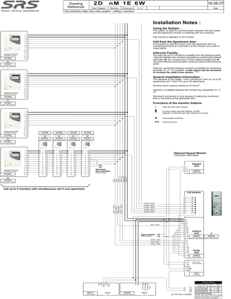
2D Drawing Reference nM 1E 6W Video Diagram Monitors Entrances 16.08.07 6+n Date One entrance video door entry system - calling n monitors Installation Notes : Using the System : The system is used for communication between the door panel and the apartment monitor in buildings with one entrance. Some terminals NOT SHOWN for clarity. 001656 mono video monitor 1 2 3 4 5 6 7 9 10 11 12 13 Call volume is adjusted on the monitor Call from the Apartment door : It is possible to call the monitor from the apartment door by connecting terminal 9 to terminal 5 at the monitor via a push to make button. Intercom Facility : You may call up to 5 monitors in parallel from the entrance panel. Intercom between the monitors is possible by pressing the internal call button . Do not push the button before pressing the since the internal communication would be heard at the entrance panel or 001657 colour video monitor Some terminals NOT SHOWN for clarity. 001656 mono video monitor Intercom connection between monitors is possible by connecting terminals 10, 11, 12 in parallel. In this case it may be necessary to increase the cable cross section. **** 1 2 3 4 5 6 7 9 10 11 12 13 General Installation Information : The diameter of the cables 1 and 2 should be 1mm2 for up to 20 apartments and 1.5mm2 for up to 40 apartments. All other wires must be minimum of 0.5mm2. Intercom is available between the monitors by connecting 10, 11, 12 Terminal 9 connection is only required if calling the monitor(s) from a call button at the apartment door or Functions of the monitor buttons 001657 colour video monitor View the main door camera Some terminals NOT SHOWN for clarity. 001656 mono video monitor 1 2 3 4 5 6 7 9 10 11 12 13 Function button (eg stair lighting, call lift). Defaults to view the main door camera if not used. Call parallel monitor(s) Unlock the door 001656 001656 001656 mono video monitor mono video monitor mono video monitor or or or or 001657 or 001656 mono video monitor colour video monitor 001657 colour video monitor 001657 colour video monitor 001657 colour video monitor 001657 colour video monitor 1 2 3 4 5 6 7 9 10 11 12 13 Optional Keypad Module Connection information Apartment door call button audio 001657 colour video monitor 008533 keypad module video 0V Push to Make or Keypad Unit 1 2 5 video 24V 1 2 3 4 5 6 7 9 10 11 12 13 audio +ve 1 2 3 4 5 6 7 9 10 11 12 13 audio -ve 001656 mono video monitor 1 2 3 4 5 6 7 9 10 11 12 13 video Some terminals NOT SHOWN for clarity. 1 2 3 4 5 6 7 9 10 11 12 13 Call up to 5 monitors with simultaneous call in one apartment. Call buttons White / Green White / Blue Blue / White Green / White Orange / White Orange / White Orange / White Orange / White Orange / White Blue / White Egress Button Push to Make White / Green White / Blue Green / White 1 2 5 6 14 15 16 17 19 Camera Unit or 008535 mono video module 4 5 7 14 15 16 17 18 14 15 N/C COM N/O 008536 colour video module Audio Unit 008540 audio module Cut link for 24V operation 9334 2 pole relay 9307/1 power supply Mains Open A B Normally C Control 002395 video power supply Common 1 2 C Z DC 0 AC Locking Options connect common Power Relay of relay to 0V connection connection 12V AC fail locked AC N/O 12V DC fail locked DC N/O 12V DC fail open DC N/C Mains 12V DC FAIL LOCKED Access Control interface Connect relay output COM & N/O to egress input on access control. Do not connect COM to 0V as shown on the diagram
