GSM ARCHITECTURE
advertisement
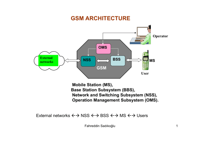
GSM ARCHITECTURE Operator OMS External networks BSS NSS MS GSM User Mobile Station (MS), Base Station Subsystem (BBS), Network and Switching Subsystem (NSS), Operation Management Subsystem (OMS). External networks ÅÆ NSS ÅÆ BSS ÅÆ MS ÅÆ Users Fahreddin Sadıkoğlu 1 PSTN PSTN ISDN ISDN AS AS VLR VLR PSDN PSDN HLR HLR NSS EIR EIR MSC MSC PLMN PLMN OMS OMS Asub interface BSC BSC BSS Abis interface BTS BTS Um interface MS Fahreddin Sadıkoğlu SIM 2 BSS components and interfaces BTS OSS BTS BSC BTS NSS Asub interface Abis interface Radio interface (Um) Message Signalling Figure 4.12 Fahreddin Sadıkoğlu 3 Base Station TRXn . BSC . TRX2 TRX1 Fahreddin Sadıkoğlu 4 BLOCK DIAGRAM OF A BASE STATION A-bis 64 kbits Receiver A Speech 8/13 bit Codec 13/8 bit Equalizer Mod./Dem. D A law 13 kbits VCO Synthesizer Control Unit 64kbits Channel Codec Signaling 16 kbits Transmitter A D Burst building Multip./Dem. BTS Fahreddin Sadıkoğlu Speech 8/13 bit Codec 13/8 bit 64 kbits BSC 5 Radio Frequency channels for GSM D900 890-915 MHz for uplink, MC to BS 935-960 MHz for downlink, BS to MS fup(n)=(890+0,2xn) MHz (with,ARFCN 1≤n≤124) fdown(n)=fup(n)+45MHz Radio frequency channel spacing: 200 kHz; Duplex spacing: 45 MHz CHANNEL DISTRIBUTION FOR D900 Uplink 001 002 Downlink 123 890 890.2 124 914.8 915 001 002 935 935.2 123 124 959.8 960 200 kHz Channel spacing Duplex spacing 45 MHz Fahreddin Sadıkoğlu 6 GSM EXTENDED BAND (E-GSM 900) 880-915 MHz for uplink ; 925-960 MHz for downlink With FDMA 124 (174 for extended band ) Fup(n)=(890+0.2 x n)MHz (with ARFCN 0≤n≤124 ) and fup(n)=(890+0,2xn) (n-1024) (with ARFCN 975≤n≤1023) fdown (n)=fup (n)+45 MHz Radio frequency channel spacing: 200 kHz; Duplex spacing: 45 MHz GSM 1800 1710-1785 MHz for uplink; 1805-1880 MHz for downlink Duplex spscing is 95 MHz with 374 channels 200 kHz spacing Numberd with 512-885 fup(n)=(1710+0,2xn) (n-511) (with,ARFCN 512≤n≤885 fdown(n)=fup(n)+95MHz Fahreddin Sadıkoğlu 7 GSM FRAME STRUCTURE Hyper Frame 0 2047 1 Duration 3.48 s 0 Super Frame 42 1 43 44 45 46 47 48 49 50 Duration 6.12 s Multiframe 0 0 3 Time Slot ST 17 1 1 2 3 57 Data 4 1 18 5 6 26 Training S 19 20 21 22 23 24 1 57 S Data 3 25 Duration 120 ms 1250 bits; Duration 4.615ms 7 24 8.25 SP 156.25 bits G ST:Start Bits S:Stealing Bit SP:Stop Bits G:Guard Bits Duration 0.57692 ms Normal burst 3 TB 57 1 Data SF 26 T 1 57 SF Data 3 8.25 TB G Fahreddin Sadıkoğlu TB:Tail Bits S:Stealing Bit SP:Stop Bits G:Guard Bits 8 Control Channels CCH ( Control Channels ) DCCH SDCCH FACCH BCCH ACCH SACCH BCCH Synch. SCH FCH CCCH RACH CBCH PCH/AGCH Fahreddin Sadıkoğlu 9 GSM PHYSICAL LAYER Microphone ADC Microphone ADC LPC-PEA Linear Predictive cooding Rgular Pulse Excitation Analysis Long-Term Prediction Shufling Interleaving Decreases possibility of distortion of consecitive bits in radio channel Speech coding Channel cooding Cyclic and Convolutional codes for error detection and correction purpose Ciphering Is used to protect data Ki+Rand A8 Kc Modulation GMSK Speech Decoding DeShufling DeInterleaving Channel decooding Deciphering Demodulation Channel Fahreddin Sadıkoğlu 10 Speech and Channel Coding 0.3-3.4 kHz BPF M fs =8kHz; 13 bits 104 kbs A Speech Encoder D 13kbs To Modulator Channel Coding 22.8 kbs From Demodulator LPF A Speech Decoder D Speech Block Filters 1 5 . 37 1 2 3 4 2 6 . 38 Every 20 ms 160 samples 3 7. 39 4 8. 40 Channel Decoder Encoder Selection Sequence with maximal energy Linear Predictive Coding and Regular Pulse Extantion –LPC/RPE Channel Cyclic Coding For error detection 189 bits Si Correlation analysis C(Si, Si-k)=max Β= Si-Si-k Β Long Term Prediction-LTP Encoder Convolutional Coding for 1 bit error correction 456 bits Fahreddin Sadıkoğlu Reordering Restructuring Interliving 11 GMSK MODULATION Sin 2πfct I(t) COS(c(t)) d(t) Integrater di(t) Gaussian Filter X + C(t) Q(t) Sin(c(t)) m(t) X Cos 2πfct I ( t ) = cos( c ( t )); Q ( t ) = sin( c ( t )) m ( t ) = I ( t ) sin 2 π fct + Q ( t ) cos 2 π fct Fahreddin Sadıkoğlu 12 AUTHOINTICATION MS Network Um Interface MS SRES Rand Ki A3 Algorithm =? SRES Yes/No DATA CIPHERING Ki MS MS Kc Rand A8 Data A5 Network Um Interface Kc Cipherd Data A5 Data Kc Fahreddin Sadıkoğlu 13 Convolutional Coding Fahreddin Sadıkoğlu 14 Functional Sequence of Basic Call Types Mobile Originated Call (MOC) to the fixed network Before an MOC begins a location registration and with it an authentication must have taken place.The MS sends the call setup information dialed by the mobile subcriber to the MSC (1). The MSC requests call information from the VLR (mainly about any relevant restictions) concerning the mobile subscriber identified by the IMSI (2). After assigning a traffic channel, the MSC then informs PSTN. Calling subscriber MS 1 Called subscriber BSS BTS/BSC/TRAU 1 VLR 2 NSC MSC 3 PSTN PST N PLMN Fahreddin Sadıkoğlu Figure 4.16 15 Mobile Internal Call (MIC) The MS1 sends the call setup information dialed by the mobile subscriber (MSISDN) to the MSC (1). The MSC requests informaton about the calling mobile subscriber MS2 from the VLR (2). The MSC uses the dialling information (MSISDN) to establish the HLR and sets up signalling connection to it (3). The HLR sends a request to the VLR in whose area the called mobile subscriber MS2 is currently roaming (4). The VLR sends the requested MSRN back to the HLR. The HLR forwards the MSRN to the MSC (5). Steps (6) to (9) are the same as steps (6) to (9) in Figure 7.17. MS2 MS1 Called subscriber Calling subscriber 1 8 7 1 BTS/BSC/TRAU BTS/BSC/TRAU 8 9 BTS/BSC/TRAU 8 BSS 7 9 1 MSC 2 3 VLR 4 NSC 6 5 5 HLR Fahreddin Sadıkoğlu PLMN 16 Mobile Terminating Call (MTC) From The Fixed Network A call for mobile subscriber arrives at the GMSC (1). The GMSC uses the dialing information (MSISDN) to es tablish the HLR and sets up a signaling connection to it (2). The HLR sends a requested VLR in whose area the called subscriber is currently roaming (3). The VLR sends the requested MSRN back to the HLR. The HLR forwards the MSRN to the GMSC (4). On the basis of the MSRN the GMSC sets up the connection request to the MSC, i.e. the MSC in whose area the mobile subcriber is roaming at this point in time (5). As the MSC does not know the mobile subscriber up to this point, the MSC requests the mobile subscriber information for the call setup from ıts VLR (6). The MS is now called by means of paging to all BTS/BSCs in the locatıon area, as the radio cell in which the MS is located is not known to the MSC (7). If there is a response to the paging, this information is transmitted to the MSC (8). Finally the connection to the MS is set up (9). Figure7.17 shows the call sequence of an MTC . Called subscriber MS 8 7 BTS/BSC/TRAU BTS/BSC/TRAU 7 4 8 7 VLR 6 3 VLR 9 9 BTS/BSC/TRAU 7 BSS NSC MSC 5 2 GMSC Calling subscriber 1 4 PLMN Fahreddin Sadıkoğlu 17
