7.1 Grinding
advertisement
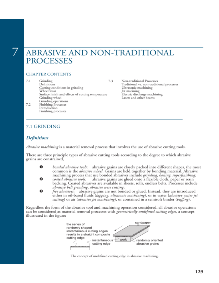
7 ABRASIVE AND NON-TRADITIONAL PROCESSES CHAPTER CONTENTS 7.1 7.2 Grinding 7.3 Definitions Cutting conditions in grinding Wheel wear Surface finish and effects of cutting temperature Grinding wheel Grinding operations Finishing Processes Introduction Finishing processes Non-traditional Processes Traditional vs. non-traditional processes Ultrasonic machining Jet macining Electric discharge machining Lasers and other beams 7.1 GRINDING Definitions Abrasive machining is a material removal process that involves the use of abrasive cutting tools. There are three principle types of abrasive cutting tools according to the degree to which abrasive grains are constrained, bonded abrasive tools: abrasive grains are closely packed into different shapes, the most common is the abrasive wheel. Grains are held together by bonding material. Abrasive machining process that use bonded abrasives include grinding, honing, superfinishing; coated abrasive tools: abrasive grains are glued onto a flexible cloth, paper or resin backing. Coated abrasives are available in sheets, rolls, endless belts. Processes include abrasive belt grinding, abrasive wire cutting; free abrasives: abrasive grains are not bonded or glued. Instead, they are introduced either in oil-based fluids (lapping, ultrasonic machining), or in water (abrasive water jet cutting) or air (abrasive jet machining), or contained in a semisoft binder (buffing). Regardless the form of the abrasive tool and machining operation considered, all abrasive operations can be considered as material removal processes with geometrically undefined cutting edges, a concept illustrated in the figure: The concept of undefined cutting edge in abrasive machining. 129 130 Grinding Valery Marinov, Manufacturing Technology Abrasive machining can be likened to the other machining operations with multipoint cutting tools. Each abrasive grain acts like a small single cutting tool with undefined geometry but usually with high negative rake angle. Abrasive machining involves a number of operations, used to achieve ultimate dimensional precision and surface finish. From the principal abrasive operations, grinding is covered in the present section, and some other operations are discussed in the next two sections. Grinding is a material removal process in which abrasive particles arc contained in a bonded grinding wheel that operates at very high surface speeds. The grinding wheel is usually disk shaped and is precisely balanced for high rotational speeds. Cutting conditions in grinding The geometry of grinding is shown in the figure: The geometry of surface grinding showing the cutting conditions. The cutting velocity V in grinding is very high. It is related to the rotational speed of the wheel by V = πDN where d is the wheel diameter, and N is the rotational speed of the grinding wheel. Depth of cut d is called infeed and is defined as the distance between the machined and work surfaces. As the operation proceeds, the grinding wheel is fed laterally across the work surface on each pass by the workpart. The distance at which the wheel is fed is called a crossfeed. The crossfeed is actually the width of cut w. The crossfeed multiplied by infeed determines the cross-sectional area of cut, CSA: CSA = crossfeed×infeed = wd The cross-sectional area in grinding is relatively small compared to other traditional machining operations. The workpart moves past the wheel at a certain linear or rotational velocity called a feed Vw. The material removal rate, mrr, is defined by mrr = VwCSA Valery Marinov, Manufacturing Technology Grinding 131 Wheel Wear Three mechanisms are recognized as the principal causes of wear in grinding wheels: grain fracture, attritious wear, and bond fracture. Grain fracture occurs when a portion of the grain breaks off but the rest of the grain remains bonded in the wheel. The edges of the fractured area become new sharp cutting edges on the grinding wheel. This makes the grinding wheel self-sharpening, a unique property of a cutting tool. Attritious wear involves dulling of the individual grains, resulting in flat spots and rounded edges. Attritious wear is analogous to tool wear in a conventional cutting tool. Bond fracture occurs when the individual grains are pulled out of the bonding material. Bond fracture usually occurs because the grain has become dull due to attritious wear and the resulting cutting force is excessive. Sharp grains cut more efficiently with lower cutting forces; hence, they remain attached in the bond structure. Surface finish and effects of cutting temperature Abrasive operations are performed to achieve a surface finish, which cannot be achieved by conventional machining processes. From the concept of composite cutting edge, it can be concluded that the surface finish is basically affected by the following process and tool parameters, v v v Abrasive grain size: smaller grit size will produce lower surface roughness; Structure: more dense structure of the grinding will, i.e., more abrasive grains per cubic millimetre will increase the number of active grains in contact with the work surface thus improving the surface finish; Cutting velocity: The surface finish will be improved by increasing the number of abrasive grains per unit time, therefore by increasing the cutting speed. The ultimate surface finish in grinding with fine grit size is about 0.2 µm. The influence of these parameters is deducted from simple geometrical considerations. But in a discussion on surface finish in grinding, the influence of the cutting temperature cannot be omitted. Temperature rise in grinding can significantly affect surface properties. Furthermore, the heat generated and conducted into the workpiece expands the workpart and causes dimensional errors. v Tempering: excessive temperatures can temper and soften the material on the surfaces, which is often ground in the hardened state. v Burning: if the temperature is excessive the surface may burn. Burning produces a bluish color on steels, which indicates high temperature oxidation with all the negative changes in the surface material properties. v Thermal cracks: high temperatures may also lead to thermal cracking of the surface of the workpiece. Cracks are usually perpendicular to the grinding direction; however, under severe grinding conditions, parallel cracks may also develop. v Residual stresses: temperature change and gradients within the workpiece are mainly responsible for residual stresses in grinding. Excessive temperature has a negative effect on the work surface. Grinding process parameters must therefore be chosen carefully to avoid excessive temperature rise. The use of grinding fluids can effectively control cutting temperatures. 132 Grinding Valery Marinov, Manufacturing Technology Grinding wheel A grinding wheel consists of abrasive particles and bonding material. The bonding material holds the particles in place and establishes the shape and structure of the wheel. (Right) The structure of a grinding wheel showing the cutting action of abrasive grains. (Left) The rake angle of a single grain can be zero or positive but usually is highly negative. The way the abrasive grains, bonding material, and the air gaps are structured, determines the parameters of the grinding wheel, which are v v v v v abrasive material, grain size, bonding material, wheel grade, and wheel structure. To achieve the desired performance in a given application, each parameter must be carefully selected. Abrasive materials The abrasive materials of greatest commercial importance today are listed in the table: Abrasive material Work material Color Aluminum oxide 97-99% Al2O3 87-96% Al2O3 hardened steels, HSS steels, cast iron white pink to brown Silicon carbide 96-99% SiC <96% SiC HSS, cemented carbides aluminum, brass, brittle materials green black Cubic boron nitride (CBN) tool steels, aerospace alloys Synthetic diamond ceramics, cemented carbides Grain size The grain size of the abrasive particle is an important parameter in determining surface finish and material removal rate. Small grit sizes produce better finishes while larger grain sizes permit larger material removal rates. Valery Marinov, Manufacturing Technology Grinding 133 The abrasive grains are classified in a screen mesh procedure, as explained in Section 3.2. In this procedure smaller grit sizes have larger numbers and vice versa. Grain sizes used in grinding wheels typically range between 6 and 600. Grit size 6 is very coarse and size 600 is very fine. Finer grit sizes up to 1000 are used in some finishing operations (Section 7.2). Bonding Materials The bonding material holds the abrasive grains and establishes the shape and structural integrity of the grinding wheel. Desirable properties of the bond material include strength, toughness, hardness, and temperature resistance. Bonding materials commonly used in grinding wheels include the following: v v v v v vitrified bond: vitrified bonding material consists chiefly of ceramic materials. Most grinding wheels in common use are vitrified bonded wheels. They are strong and rigid, resistant to elevated temperatures, and relatively unaffected by cutting fluids; rubber bond: rubber is the most flexible of the bonding materials. It is used as a bonding material in cutoff wheels; resinoid bond: this bond is made of various thermosetting resin materials. They have very high strength and are used for rough grinding and cutoff operations; shellac bond: shellac-bonded grinding wheels are relatively strong but not rigid. They are often used in applications requiring a good finish; metallic bond: metal bonds, usually bronze, are the common bond material for dia mond and CBN grinding wheels. Diamond and CBN abrasive grains are bond material to only the outside periphery of the wheel, thus conserving the costly abrasive materials. Wheel grade Wheel grades indicates the wheel bond strength. It is measured on a scale ranging from soft to hard. Soft wheels loose grains easily and are used for low material removal rates and grinding of hard materials. Harder grades are preferred for high productivity and grinding of relatively soft materials, Structure The wheel structure indicates spacing of the abrasive grains in the wheel. It is measured on a scale that ranges from open to dense. Open structure means more pores and fewer grains per unit wheel volume, and vice versa. Open structure is recommended for work materials that tend to produce continuous chips, while denser structure is used for better surface finish and dimensional precision. Grinding wheel specification Grinding wheels are marked with a standardized system of letters and numbers, which specifies the parameters of the grinding wheel. Grinding wheels are available in a variety of shapes and sizes the most popular shown in the figure: Some common types of grinding wheels; (From left to right) straight, cylinder, straight cup, flaring cup, mounted. 134 Grinding Valery Marinov, Manufacturing Technology Grinding operations Grinding operations are carried out with a variety of wheel-workpart configurations. The basic type of grinding are v v v surface grinding, cylindrical grinding, and centerless grinding. Each basic operation has a number of variations some of them discussed in this section. Surface grinding Surface grinding is an abrasive machining process in which the grinding wheel removes material from the plain flat surfaces of the workpiece. abrasive primary wheel motion chips work tion mo d e fe Surface grinding. In surface grinding, the spindle position is either horizontal or vertical, and the relative motion of the workpiece is achieved either by reciprocating the workpiece past the wheel or by rotating it. The possible combinations of spindle orientations and workpiece motions yield four types of surface grinding processes illustrated in the figure: Four types of surface grinding with horizontal or vertical spindles, and with reciprocating linear motion or rotating motion of the workpiece. Valery Marinov, Manufacturing Technology Grinding 135 Of the four types, the horizontal spindle machine with reciprocating worktable is the most common: Surface grinder with horizontal spindle and reciprocating worktable. Cylindrical grinding In this operation, the external or internal cylindrical surface of a workpiece are ground. In external cylindrical grinding (also center-type grinding) the workpiece rotates and reciprocates along its axis, although for large and long workparts the grinding wheel reciprocates. In internal cylindrical grinding, a small wheel grinds the inside diameter of the part. The workpiece is held in a rotating chuck in the headstock and the wheel rotates at very high rotational speed. In this operation, the workpiece rotates and the grinding wheel reciprocates. Cylindrical grinding. Two types of surface grinding, (Left) external, and (Right) internal. 136 Grinding Valery Marinov, Manufacturing Technology Three types of feed motion are possible according to the direction of feed motion, traverse feed grinding (also through feed grinding, cross-feeding) in which the relative feed motion is parallel to the spindle axis of rotation, plunge grinding in which the grinding wheel is fed radially into the workpiece, and a combination of traverse and plunge grinding in which the grinding wheel is fed at 45o to grind simultaneously the cylindrical part of the workpiece and the adjacent face. This methods provides a precise perpendicular mutual position of both surfaces. Three types of cylindrical grinding: (From left to right) traverse feed grinding, plunge grinding, a combination of both previous types. In universal cylindrical grinders, both the workpiece and the grinding wheel axis can be swivelled around a horizontal plane, permitting all these types of cylindrical grinding. Universal cylindrical grinder. Centerless grinding Centerless grinding is a process for continuously grinding cylindrical surfaces in which the workpiece is supported not by centers or chucks but by a rest blade. The workpiece is ground between two wheels. The larger grinding wheel does grinding, while the smaller regulating wheel, which is tilted at an angle i, regulates the velocity Vf of the axial movement of the workpiece. Centerless grinding can also be external or internal, traverse feed or plunge grinding. The most common type of centerless grinding is the external traverse feed grinding, illustrated in the figure: Valery Marinov, Manufacturing Technology Grinding 137 External traverse feed centerless grinding. The regulating wheel is tilted at an angle i to control the velocity of through feed. The centerless grinding is ideal for mass production. It requires special machines that can do no other type of work: External centerless grinder. Typical parts made by centerless grinding are roller bearings, piston pins, shafts, and similar components. Parts with variable diameters, such as bolts, valve tappets, and distributor shafts, can be ground by plunge centerless grinding. Sleeve-shaped parts and rings can be ground by the internal centerless grinding, in which the workpiece is supported between three rolls and is internally ground. Creep-feed grinding Grinding has traditionally been associated with small rates of material removal and finishing operations. However, grinding can also be used for large-scale metal removal operations similar to milling, shaping, and planing. In creep-feed grinding, the depth of cut d is as much as 6mm, and the workpiece speed is low. The wheels are mostly softer grade resin bonded with open structure to keep temperatures low. Creep-feed grinding can be economical for specific applications, such as grinding cavities, grooves, etc.
