Lab 4: Electron Diffraction
advertisement
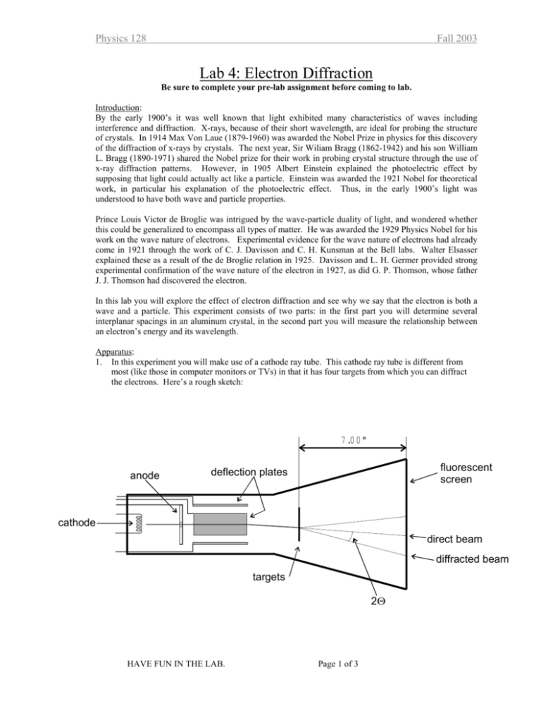
Physics 128 Fall 2003 Lab 4: Electron Diffraction Be sure to complete your pre-lab assignment before coming to lab. Introduction: By the early 1900’s it was well known that light exhibited many characteristics of waves including interference and diffraction. X-rays, because of their short wavelength, are ideal for probing the structure of crystals. In 1914 Max Von Laue (1879-1960) was awarded the Nobel Prize in physics for this discovery of the diffraction of x-rays by crystals. The next year, Sir Wiliam Bragg (1862-1942) and his son William L. Bragg (1890-1971) shared the Nobel prize for their work in probing crystal structure through the use of x-ray diffraction patterns. However, in 1905 Albert Einstein explained the photoelectric effect by supposing that light could actually act like a particle. Einstein was awarded the 1921 Nobel for theoretical work, in particular his explanation of the photoelectric effect. Thus, in the early 1900’s light was understood to have both wave and particle properties. Prince Louis Victor de Broglie was intrigued by the wave-particle duality of light, and wondered whether this could be generalized to encompass all types of matter. He was awarded the 1929 Physics Nobel for his work on the wave nature of electrons. Experimental evidence for the wave nature of electrons had already come in 1921 through the work of C. J. Davisson and C. H. Kunsman at the Bell labs. Walter Elsasser explained these as a result of the de Broglie relation in 1925. Davisson and L. H. Germer provided strong experimental confirmation of the wave nature of the electron in 1927, as did G. P. Thomson, whose father J. J. Thomson had discovered the electron. In this lab you will explore the effect of electron diffraction and see why we say that the electron is both a wave and a particle. This experiment consists of two parts: in the first part you will determine several interplanar spacings in an aluminum crystal, in the second part you will measure the relationship between an electron’s energy and its wavelength. Apparatus: 1. In this experiment you will make use of a cathode ray tube. This cathode ray tube is different from most (like those in computer monitors or TVs) in that it has four targets from which you can diffract the electrons. Here’s a rough sketch: 7 .0 0 " anode fluorescent screen deflection plates cathode direct beam diffracted beam targets 2Θ HAVE FUN IN THE LAB. Page 1 of 3 Physics 128 Fall 2003 Experiment: 1. To begin, (a) Turn the accelerating voltage and the intensity all the way down. (b) Turn on the power. Wait for a few minutes for the cathode to warm up. (c) Turn up the accelerating voltage to 10 kV. (d) Slowly turn up the intensity, KEEPING THE CURRENT BELOW 10 µA. Use the minimum intensity needed for good viewing. Keep the current to 10µA or below. 2. By applying a varying voltage across two sets of deflection plates, you can steer the electron beam to hit any of four grids. [Make sure you know where the grids are.] The grid you will work with the most has polycrystalline Al on it. Its diffraction image will be located in the lower left-hand quadrant of the phosphor screen. Do not let the undiffracted beam sit in one place for too long a time since this will damage the screen. 3. With the accelerating voltage set to 10kV, steer the beam until you find the diffraction pattern of the polycrystalline Al. It will consist of several concentric circles. Adjust the focus. Check the accelerating voltage and trim it to 10kV. 4. At this point you will need to understand why the diffraction pattern consists of circles. What other patterns might you expect? Discuss this point with your instructor. 5. Make a few measurements of the diameter of each of the concentric circles. Trim the accelerating voltage to 10kV before each measurement. [Later you will want to make a neat table of the diameters of the circles (and their uncertainty), the associated diffraction angle, and the associated d-spacing of the Al crystal, so leave lots of space in your notebook for making the table.] 6. Vary the accelerating voltage from 10 kV to 5 kV in increments of 1 kV. At each voltage, adjust the position and focus to get a good diffraction pattern. Measure the diameters (a few times again) for as many of the diffraction rings as possible. [Again, leave lots of space in your notebook because you will want to use these measurements, determine the diffraction angle associated with them and then using the "known" values of the interplanar spacings, calculate the electron’s wavelength at each accelerating voltage.] 7. Before you finish look at the diffraction pattern the other targets. 8. When you’re done, turn down the intensity and accelerating voltage all the way and then turn off the power. Analysis: 1. In your lab notebook, make a neat table of the measured diameters, the scattering angle and the interplanar spacing for each circle (including uncertainties). In order to do this, make a provisional determination of the electron wavelength using the accelerating voltage and the theoretical relationship between the kinetic energy and wavelength. Compare your results for the interplanar spacings with the "known" values. 2. Now that you have identified which circles belong to which d-spacings, use your measurments of the scattering angle and the “known” d-spacings to determine the wavelength of the electrons. Using your measurements from part 6 above, determine the electron wavelength for each accelerating voltage. Plot the wavelength vs. the kinetic energy of the electrons. Use your measured value of the accelerating potential and the theoretical relationship between the kinetic energy and wavelength to determine a “theoretical value” of the wavelength. See how your measured results compare with this predicted variation. HAVE FUN IN THE LAB. Page 2 of 3 Physics 128 Fall 2003 Report: For this lab you will write a full report. It will be due two weeks from the day that you conduct your experiment. Please refer to the Lab Report Handout for further details. In your report you should answer the following questions: • • • • • Why is the cathode ray tube evacuated? Why does changing the accelerating voltage cause the undiffracted beam to drift? Why does the diffracted beam from the Al crystal form a circle on the screen rather than distinct points? How does changing the accelerating voltage affect the diameter of the diffraction rings? Why? In what way does this experiment prove that electrons can behave like waves? Allowed reflections for FCC and d-spacing for Al (lattice constant = 0.405 nm) The letters (h,k, l) are called Miller indices and help label distinct planes in the crystal. hkl h2 + k 2 + l 2 111 200 220 311 222 400 331 420 422 511, 333 440 531 3 4 8 11 12 16 19 20 24 27 32 35 HAVE FUN IN THE LAB. (h 2 +k2 +l2 1.732 2.000 2.828 3.316 3.464 4.000 4.358 4.472 4.898 5.196 5.656 5.916 ) 1/ 2 d (nm) 0.234 0.203 0.143 0.122 0.117 0.101 0.0929 0.0906 0.0827 0.0779 0.0716 0.0685 Page 3 of 3 Electron Diffraction Pre-Lab Exercise 1. In next week's lab you will observe the diffraction of electrons. This proves that electrons can behave like waves. Before we begin the lab with let's review Bragg diffraction by working through the problem below. Recall that when you shine a monochromatic wave source onto a periodic array of scattering centers (like light onto atoms in a crystal), the diffracted waves interfere constructively when the Bragg condition is met. First let’s derive the Bragg condition. (a) Recall the problem of the diffraction grating we worked out in lab last week. You showed that for waves scattered from a series of scattering centers that form a line (they may be scratches on a grating or atoms in a crystal), the condition for constructive interference is given by d cos β − d cos α = mλ (1) where the angles are shown below. [You should make sure that you can derive this expression. See the lab handout for the atomic spectra lab if you’re having trouble.] α β d Now, consider two such planes spaced by the distance d’ as shown below. By considering the path length difference between the waves that scatter from the first plane and those that scatter from the second plane, show that the condition for the constructive interference of these waves is given by (2) d ′ sin α + d ′ sin β = nλ where n is also an integer that may or may not be equal to m. α d’ β (b) Now, in order for constructive interference both (1) and (2) must hold simultaneously. It can be shown that in general, these conditions can be met by planes of atoms (not necessarily parallel to those shown above) for which the incident angle is equal to the scattered angle. Show that for the special case of α = β, both (1) and (2) can be satisfied and lead to the Bragg condition. (c) You have demonstrated that if the Bragg condition is met, waves scattered from two adjacent planes are in phase and this leads to constructive interference. What about the waves scattering from other planes? Consider the following statement. “OK, I see that if the Bragg condition is met for the first two planes, it is met for all planes parallel to the first two as well. Then the waves scattered from all the planes are in phase. But suppose that the waves from the first two are just a tiny bit out of phase, shouldn’t they still mostly interfere? Shouldn’t I get a Bragg peak?” Explain why the last two sentences of this statement are incorrect. (d) For the square lattice pictured below, find at least three distinct, non-parallel Bragg planes. For set of planes, calculate the distance between the planes d. d0=0.45 nm (e) If a wave with λ=0.154 nm is incident on the lattice above from any direction, calculate the scattering angles (first order only) for which the Bragg condition is met. Find at least three distinct angles. Using arrows like those in the figures in part (a), indicate the direction of the incident and scattered waves, for each case. Now for a little review of electrons. (f) Recall that the energy E, momentum p, and mass m, of a relativistic particle are related by the relation ( ) 2 ( ) E 2 = K + mc 2 = ( pc )2 + mc 2 Knowing that p=h/λ, solve for λ as a function of K and m. 2 (g) Using some software, calculate λ for the following values of the kinetic energy: K=1 eV, 10 eV, 100 eV, …1 GeV. Display your results on a log-log plot.


