Phase Diagrams Question Sheet 2 Problems and Answers
advertisement
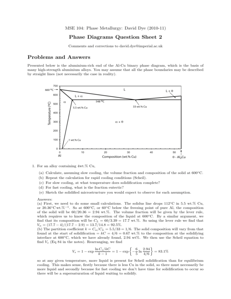
MSE 104: Phase Metallurgy: David Dye (2010-11) Phase Diagrams Question Sheet 2 Comments and corrections to david.dye@imperial.ac.uk Problems and Answers Presented below is the aluminium-rich end of the Al-Cu binary phase diagram, which is the basis of many high-strength aluminium alloys. You may assume that all the phase boundaries may be described by straight lines (not necessarily the case in reality). 700 660 oC L Temperature (oC) 600 L+θ L+α 548 oC α 500 33 wt.% Cu 5.5 wt.% Cu 400 α+θ 300 200 100 1 wt.% Cu 0 0 10 Al 20 30 Composition (wt.% Cu) 40 50 θ - Al2Cu 1. For an alloy containing 4wt.% Cu, (a) (b) (c) (d) (e) Calculate, assuming slow cooling, the volume fraction and composition of the solid at 600◦ C. Repeat the calculation for rapid cooling conditions (Scheil). For slow cooling, at what temperature does solidification complete? For fast cooling, what is the fraction eutectic? Sketch the solidified microstructure you would expect to observe for each assumption. Answers: (a) First, we need to do some small calculations. The solidus line drops 112◦C in 5.5 wt.% Cu, or 20.36◦ C wt.%−1 . So at 600◦ C, or 60◦ C below the freezing point of pure Al, the composition of the solid will be 60/20.36 = 2.94 wt.%. The volume fraction will be given by the lever rule, which requires us to know the composition of the liquid at 600◦C. By a similar argument, we find that its composition will be CL = 60/3.39 = 17.7 wt.%. So using the lever rule we find that Vα = (17.7 − 4)/(17.7 − 2.9) = 13.7/14.8 = 92.5%. (b) The partition coefficient k = Cα /CL = 5.5/33 = 1/6. The solid composition will vary from that found at the start of solidification = kC = 4/6 = 0.67 wt.% to the composition at the solidifying interface at 600◦C, which we have already found, 2.94 wt%. We then use the Scheil equation to find Vs (Eq 84 in the notes). Rearranging, we find 6 2.94 ln Cs /kC = 83.1% = 1 − exp − ln Vs = 1 − exp k−1 5 4/6 so at any given temperature, more liquid is present for Scheil solidification than for equilibrium cooling. This makes sense, firstly because there is less Cu in the solid, so there must necessarily be more liquid and secondly because for fast cooling we don’t have time for solidification to occur so there will be a supersaturation of liquid waiting to solidify. 2 MSE 104: Phase Metallurgy: David Dye (2010-11) (c) For equilibrium cooling, solidification completes when the alloy composition intersects the solidus line. This is at 660 − 20.36 × 4 = 578.6◦C. (d) For Scheil cooling, this is a repeat of (b) but where the liquid composition is the eutectic composition, or equivalently where the solid composition at the interface is 5.5 wt.%. So again 5.5 ln Cs /kC = 92.1% = 1 − exp −1.2 ln Vs = 1 − exp k−1 4/6 and so the fraction eutectic is 7.9%. (e) For slow cooling, we will just have grain of solid alpha phase. For Scheil cooling we will have grain of cored alpha surrounded by a eutectic mixture of α and θ. 2. The SnO2 –TiO2 system shows complete solid solution at high temperatures and a solvus at lower temperatures. Thermodynamic data indicate that the value of WH is 28.3 kJmol−1 in the expression for the enthalpy of mixing ∆Hmix = xS xT WH , where xS is the mole fraction SnO2 and xT is the mole fraction TiO2 . (a) Calculate ∆Hmix at xS = 0, 0.1, 0.3, 0.5, 0.7, 0.9 and 1 and plot your values on a graph of ∆Hmix against composition. (b) Calculate the entropy of mixing at the same compositions and add a curve for −∆Smix to your graph (∆Smix = −R(xS ln xS + xT ln xT ) for random mixing of Sn and Ti on their sites). (c) Calculate the Gibbs energy of mixing for these compositions at temperatures T of 1550◦C, 1300◦C and 1000◦C. Make another graph of these values. (d) From this graph, estimate the compositions of the co-existing phases in the two-phase region and hence plot the solvus on a binary phase diagram. Answer: We can make the following table: xS 0 0.1 xT = 1 − xS 1 0.9 0 2.54 (a) ∆Hmix kJ mol−1 0 -2.70 (b) −∆Smix J mol−1 (c) ∆Gmix (1823 K) J mol−1 0 -2380 (d) ∆Gmix (1573 K) J mol−1 0 -1700 -156 (e) ∆Gmix (1273 K) J mol−1 0 0.3 0.7 5.94 -5.08 -3320 -2050 864 0.5 0.5 7.08 -5.76 -3430 -1990 1312 0.7 0.3 5.94 -5.08 -3320 -2050 864 0.9 0.1 2.54 -2.70 -2380 -1700 -156 1 0 0 0 0 0 0 Note that we need to remember to do our calculations in K and mole fraction. The graphs look like this; H (kJ mol-1) 8 -S (J mol-1) xs 0 0 0.1 0.2 0.3 0.4 0.5 0.6 0.7 0.8 0.9 1 6 H -500 -S 4 -1000 2 -1500 0 1823K 0 0.1 0.2 0.3 0.4 0.5 0.6 0.7 0.8 0.9 1 -2000 xs -2500 -4 -3000 -6 -3500 -8 1573K 1273K -2 G (J mol-1) -4000 So at high temperatures, we notice that there is only on minimum and therefore there is no way to draw a common tangent between a low xS and a high xT variant of the phase to lower the overall energy of an alloy. However, at low temperatures there are two minima with a maxima in between. Therefore an alloy at (say) xS = 0.3 can lower its overall energy by decomposing into two variants of the phase. At 1000◦C, these minima are at about xS = 0.1 and 0.9. So we can draw a phase boundary so that in between 0.1 and 0.9, we have a two phase region. If we do this at every temperature, we generate the phase diagram in Figure 49. So the point of this question is that is shows us how to calculate a phase diagram from expressions for the Gibbs energy / energies of the phase or phases. MSE 104: Phase Metallurgy: David Dye (2010-11) 3 3. The MgO–FeO system shows complete solubility in both the solid and liquid phases. Values for the d420 interplanar spacing of the solid phase obtained by X-ray diffraction are given below. √ (a) MgO and FeO are cubic with a = 4.213 Å and 4.307 Å, respectively. Using dhkl = a/ h2 + k 2 + l2 , calculate d420 for the end-member (0 and 100) compositions. (b) Vegard postulated that the lattice parameter (unit cell size) of a material varies linearly with composition. Thereby determine the unknown compositions of the solid phase in the Table (ignore the possible effect of thermal expansion). (c) Hence plot the equilibrium phase diagram for the system. (d) The Figure below shows the Gibbs energy curves of the solid and liquid phases for the system. By comparison with your equilibrium diagram, determine the temperature to which it corresponds. Liquid Composition mol% MgO 0 20 40 60 80 100 Temp. ◦ C 1350 1900 2200 2500 2700 2800 Solid Solution d420 Å mol% MgO 0 0.951 0.947 0.944 0.943 100 G Solid Liquid 65% FeO mol % MgO 92% MgO Answer: (a) Plugging the numbers into the equation, d420 (MgO)= 0.942 Å and d420 (FeO)= 0.963 Å. (b) We can see that for mol% MgO=0, d420 = 0.963 in the solid, and for mol% MgO=1, d420 = 0.942, from (a). So d420 decreases by 0.021 Å as the amount of MgO in solution varies from 0 to 1. When we plot the graph, we can then just ask what mol% would give us the d-spacing found in the table, because those d-spacings must lie on that straight line.This gives us the graph below, at left. (c) We have therefore found the compositions of the solid corresponding to the given liquid compositions and can plot the phase diagram; Liquid Comp mol% MgO 0 20 40 60 80 100 Temp. ◦ C 1350 1900 2200 2500 2700 2800 Solid Composition d420 Å mol% MgO 0.963 0 0.951 57 0.947 76 0.944 90 0.943 95 0.942 100 3000 100 2500 L Temperature (oC) 90 80 mol% MgO 70 60 50 40 30 L+S 2000 1500 S 1000 500 20 10 0 0 0.94 0.945 0.95 0.955 0.96 0.965 0 20 40 60 mol% MgO 80 100 d_420 (A) (d) If we plot the common tangent on the diagram given, we find the liquid and solid compositions are 65% and 90%, which corresponds on the phase diagram to a temperature of around 2600 ◦C. 4 MSE 104: Phase Metallurgy: David Dye (2010-11) 4. You are provided below with a partial phase diagram for the TiO2 –Nb2 O5 system. (a) Designate each of the single phase fields (some have very limited solid solubility) and determine the nominal compositions of the phases. (b) Label the two phase fields and note the compositions and temperatures of the eutectic points. (c) Draw a schematic diagram of the variation of Gibbs Energy against Composition for all the phases at a temperature of 1466◦C, that is, between the lower two eutectic temperatures. Label the known compositions of the phases and draw common tangents where appropriate [hint: draw the liquid first]. Answer: (a) There are five phases; the liquid, α-Nb2 O5 , two intermediate compounds which we can denote β and γ, and finally δ-TiO2 . β has around 25% TiO2 , so the Nb2 O5 and TiO2 are in the ratio 3:1. So this compound has a content of Nb6 TiO17 . Similarly, γ is at 50:50 composition, so its composition is Nb2 TiO7 . (b) There are eutectic poinst at about 1464◦C and 20%, 1468 ◦C and 37%, and 1476◦C and 58%. (c) So the real trick here is to understand what the shapes of the Gibbs energy curves for the phases must look like. The liquid has a huge solubility range, so its Gibbs energy must vary quite gradually. β and γ, in contrast, only exist at very tightly defined compositions, so hypothetical β or γ at compositions away from that actually observed must be very unfavourable and therefore have very high energy. The α and δ solid solutions are the intermediate case: they exist over a range of compositions but not all compositions; so their Gibbs Energy curves will vary fairly sharply. The second thing we know from the phase diagram are the ranges over which the phases coexist. So at this temperature there are four two phase regions: α+L, β+L, β + γ and γ + δ. And there are three single phase regions α, L and δ. So then we draw the Gibbs energy curves for the five phases such that they form common tangents corresponding to the two phase regions, and are unconditionally the lowest energy for a single phase for the single phase solution regions. There are several ways to do this! One is given overleaf. So in this question, we have gone through the reverse process - we have related the phase diagram to the form of the Gibbs energy curves. Finally, note that the common tangent goes through points of the same gradient on the Gibbs energy curves of different phases, NOT the minima. MSE 104: Phase Metallurgy: David Dye (2010-11) 5 L 1500 γ δ+L β 1480 αss 1460 α+L γ+L β+L β+L γ+δ β+γ α+β 0 Nb2O5 δss γ+L 20 40 mol% TiO2 G (kJ mol-1) Temperature (oC) 1520 60 80 100 TiO2 γ αss δss β L αss 0 Nb2O5 α+L L β+L 20 γ+δ β+γ 40 mol% TiO2 60 δss 80 TiO2 6 MSE 104: Phase Metallurgy: David Dye (2010-11) 5. CMSX-4 is a nickel superalloy with composition Ni-6.4Cr-9.7Co-0.6Mo-1.0Ti-5.6Al-6.5Ta-6.4W0.1Hf-3.0Re (wt.%). It is composed of two phases, an fcc γ-Ni phase and a primitive cubic γ ′ phase of nominal composition Ni3 Al, where the Al atoms are placed on the cube face centres and the Ni atoms are placed on the cube corners. You may assume that the solubility of Al, Ta and Ti in the γ is nil and that these atoms are only found on the Al site in the γ ′ phase. Further, assume that Re has no solubility in the γ ′ and that all the remaining atomic species have complete solubility and partition evenly in the γ phase and on the Ni site in the γ ′ . Therefore, calculate the volume fraction of γ ′ and the compositions of each phase in at.%. To do this problem, we need to figure out and then go through a series of logical steps. (a) First, we convert to atomic % to find out the fractions of atoms in the system, following Equation 11 in the notes. (b) Then, we sum the atomic fractions of the Al, Ta and Ti. The γ ′ phase has an composition X3 Y, and the question tells us that Y = Al, Ta or Ti, whilst X = Ni, Cr, Co, Mo, W, or Hf. Also, the γ phase doesn’t contain any Al, Ta or Ti. So, the content of these atoms sets the amount of γ ′ that must be present. The total of them is 16.08 at.%, so the γ ′ fraction is 4× that, or 64.1%. (c) For the γ ′ Al site, we can normalise these values to obtain their ratio’s on that site. (d) For all the species that occur on the γ ′ Ni site, we now copy their compositions into a row; the sum of their contents is 82.9. (e) We then normalise each of these to get their ratios on the Ni site by dividing by 82.9%. So now we have the γ ′ composition - it is (Ni75.8 Cr9.0 Co12.1 Mo0.5 W2.6 Hf0.003 )3 (Al78.5 Ta13.6 Ti7.9 ). (f) Alternatively, the overall γ ′ composition is given in (f) - multiply the Ni-site components by 0.75 and the Al-site component by 0.25. (g) Now for the γ-“Ni” phase, we need to find out what we have left. For each species, we have the amount we started off with (62.91% for Ni) less the amount that is in the γ ′ (for Ni, 56.9% × 64.3%). This leaves us with 26.3 at% for Ni. The sum of these fractions is the fraction of γ phase, or 35.7%. (h) Finally, we find the ratios of those by dividing by 35.7% to find the γ composition. at. mass wt% cx/mx (a) at.% (b) γ ′ Al site (c) γ ′ Al % (d)γ ′ Ni site (e) γ ′ Ni % (f) γ ′ at% (g) γ Ni site (h) γ at% Ni 58.69 60.7 1.03 62.91 Cr 52.00 6.4 0.12 7.49 Co 58.93 9.7 0.16 10.01 Mo 95.94 0.6 0.01 0.38 62.9 75.8 56.9 26.3 73.8 7.5 9.0 6.8 3.1 8.8 10.0 12.1 9.1 4.2 11.7 0.4 0.5 0.3 0.2 0.4 Ti 47.87 1 0.02 1.27 1.27 7.9 2.0 0.0 Al 26.98 5.6 0.21 12.62 12.62 78.5 19.6 0.0 Ta 180.95 6.5 0.036 2.19 2.19 13.6 3.4 0.0 W 183.84 6.4 0.035 2.12 Hf 178.49 0.1 0.00056 0.034 Re 186.21 3 0.016 0.98 2.1 2.6 1.9 0.9 2.5 0.034 0.041 0.031 0.014 0.040 1.0 2.7 sum 100 1.6 100 16.08 100 82.9 100 100 35.7 100 So, this is actually rather a tricky question. We can make some observations; (i) it often helps to make a spreadsheet to do the arithmetic. (ii) If we make some assumptions, we can make an educated guess at the phase compositions of even quite complicated alloys. This alloy is used very heavily by Rolls-Royce to make single crystal turbine blades in jet engines - it is one of the best high temperature materials known, with oxidation and creep resistance, toughness and strength. The γ ′ phase is a very stable, very strong intermetallic that forms a fine dispersion of 10–200 nm precipitates in the alloy, imparting almost all of the high temperature strength found in the alloy. The matrix is just there to give the material some ductility, because intermetallics on their own tend to be brittle. When designing these sorts of alloys it helps to have an idea of which atoms go where. In practice, the Al, Ti and Ta elements that promote the γ ′ don’t partition this strongly, nor do the γ-formers like Mo partition so evenly. In fact, the alloy has a γ ′ fraction of about 69%; but our estimate here isn’t too bad! Another thing to notice is the dramatic effect of atomic mass. Despite there only being 5.6 wt.% Al in the alloy, it account for more than 1/8th of the atoms. Conversely, only 1 in 50 of the atoms are Ta. But, because Ta goes to the γ ′ Al site, it still accounts for about 1/8th of the atoms on that site, so its effect is quite dramatic. One final thing to notice is that although the Ni content looks quite low at around 60 wt.%, on its atomic site it is actually quite high, at around 3/4.
