Catalytic Reactor Design
advertisement
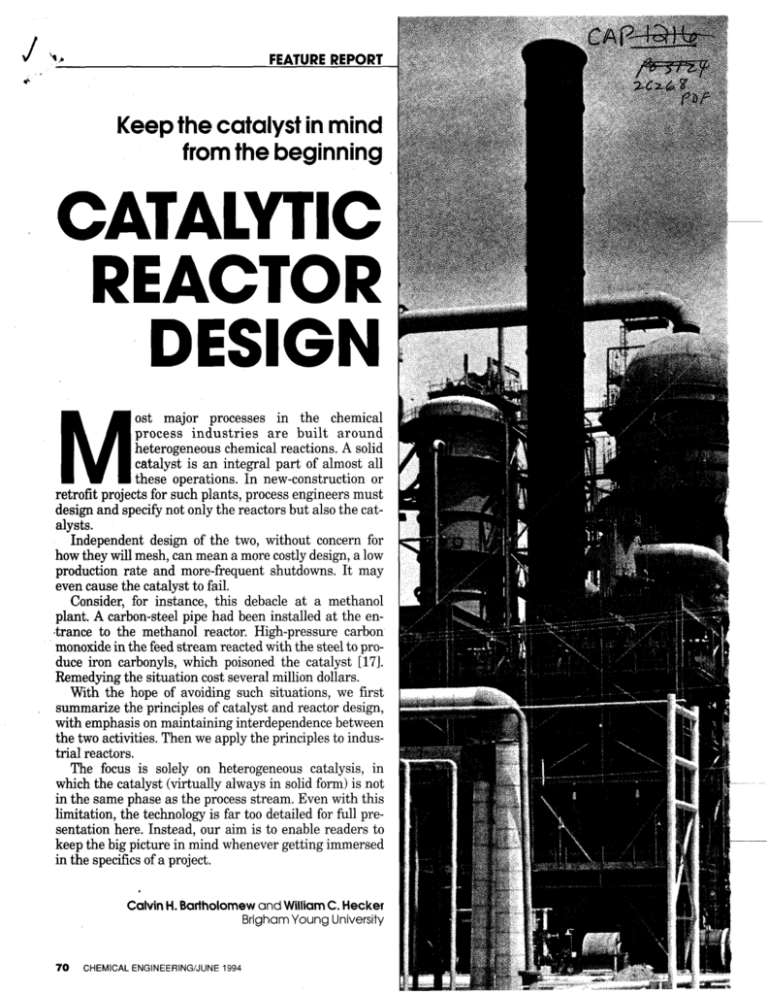
J FEATURE REP()RT Keepthe catalyst in mind from the beginning CATALYTIC REACTOR DESIGN M ost major processes in the chemical process industries are built around heterogeneous chemical reactions. A solid catalyst is an integral part of almost all these operations. In new-construction or retrofit projects for such plants, process engineers must design and specify not only the reactors but also the catalysts. Independent design of the two, without concern for how they will mesh, can mean a more costly design, a low production rate and more-frequent shutdowns. It may even cause the catalyst to fail. Consider, for instance, this debacle at a methanol plant. A carbon-steel pipe had been installed at the en,trance to the methanol reactor. High-pressure carbon monoxide in the feed stream reacted with the steel to produce iron carbonyls, which poisoned the catalyst [171. Remedying the situation cost several million dollars. With the hope of avoiding such situations, we first summarize the principles of catalyst and reactor design, with emphasis on maintaining interdependence between the two activities. Then we apply the principles to industrial reactors. The focus is solely on heterogeneous catalysis, in which the catalyst (virtually always in solid form) is not in the same phase as the process stream. Even with this limitation, the technology is far too detailed for full presentation here. Instead, our aim is to enable readers to keep the big picture in mind whenever getting immersed in the specifics of a project. Calvin H. Bartholomew and William C. Hecker BrighamYoung University 70 CHEMICAL ENGlNEERlNGiJUNE 1994 The ENR Directory of Contractors All 4 Regional Editions at $95 per set 0. Regional editions $35 for one; $55 for two; $75 for three. West Midwest 0 South 0 Northeast Price includes shipment via UPS within U.S. Add $20 for overnight delivery or shipment outside US. PREPAID OR CREDIT CARD ORDERS ONLY. a a RETURN TO: ENR DIRECTORIES - Room 4188 1221 AVENUE OF THE AMERICAS NEW YORK, NY 10020 TEL: (212) 512-4635 FAX: (212) 512-4178 Enclosed is my check for $ (Payable to ENR Directories) Charge to my credit card account: D Visa Master Card D American Express Name on card: Card No. Name: Exp. Date: Title: Company: Address: City: Phone: State: Fax: Zip: Part 1 1 t‘ Catalyst design eterogeneous catalysts come in a wide variety of forms. Most are spheres, tablets, rings, pellets of various shapes, or monolithic honeycomb structures. Generally,this particle or structure consists of an active catalytic species impregnated into or deposited onto a nominally inert support. Design involves both the active catalyst and the support. It consists essentially of choosing the right type and form of catalyst for a given situation, then specifying its size, porosity, catalytic-species distribution and other properties. This design procedure requires the engineer to deal with the catalytic functions, chemical and physical properties, and mechanical and flow properties of the catalyst. These three groupings are highly interrelated. For instance, catalytic functions include activity, selectivity for desired products, and stability against deactivation; each of these depends on the chemical and physical makeup of the catalyst. Mechanical properties, including particle strength and attrition resistance, depend on the chemical stability and microstructure of the solid and the presence of binders. And flow properties, such as flow distribution and pressure drop, depend on particle shape and size. The interrelation often generates a need for compromises. For instance, mechanical strength decreases with increasing porosity 151, especially above a porosity of 50%, whereas activity at high conversions (entailing conditions where pore diffusional resistance is high) rises with increasing porosity. Accordingly, the degree of porosity must be a compromise between high activity and high mechanical strength. Furthermore, moderately active catalysts tend to be chemically more stable than those of high activity. And pressure drop through the system is lowest for large catalyst particles, at the expense of higher pore diffusional resistance and hence lower activity. An imaginative engineer will be alert for new approaches or materials that at least partially circumvent the need for compromises. For instance, a compara- H Amencan Oil Co tively new catalyst composed of a ceramic honeycomb monolith with a thin catalyst wash-coat inside its channels provides both low pressure drop and low pore diffusional resistance, i.e., high activity. Eight steps: A stepwise procedure for catalyst design follows. The appropriate interweaving of this procedure with reactor design is explained beginning on the next page. (1) Spell out the reactants, products and operating conditions for the process (2)Identify and list all possible chemical reactions (includingundesired ones)and categorize them according to the type of bond changes. Examples of reactions include dehydrogenation, hydrogenation, oxidation, carbon monoxide insertion, dehydration, and group addition (3) Assess the feasibility and energetics of each reaction in Step 2, by calculating its enthalpy change, free-energy change and other relevant thermodynamic parameters (4)For the reactions that Step 3 shows to be significant, visualize the actual molecular changes, the elementary reactions on the catalyst surface, and the active intermediates. From this, predict the important reaction paths (5) Determine what kinds of catalytic functions or sites (for example, adsorptive, desorptive, hydrogenative, acidic) will be necessary. For instance, lowtemperature methane combustion calls for catalytic sites that dissociatively chemisorb oxygen and methane but easily desorb water (6) Seek catalyst materials that offer the appropriate catalytic functions (e.g.,platinum or nickcl for hydrogcnntion, and zeolites for cracking),the necessary thermal stability, and resistance to poisoning or fouling. Look also for a stable, compatible support material, as well as promoters to enhance activity or stability (7) Specify the catalyst microstructure in terms of crystallinity, surface area, porosity and similar parameters that govern catalyst strength and attrition resistance. Also, specify catalyst particle size and shape, and choose binders to give the particle strength and attrition resistance. In this step, keep in mind the importance of minimizing pressure drop. Apart from the decrease with increasing catalyst-particle size, the pressure drop per unit height of catalyst bed can be decreased by factors as high as ten through careful choice of monoliths or uniquely lobed or star-shaped pellets. At a constant particle diameter, pressure drop increases in the following order: lobes, rings, extrudates, tablets, spheres (8) In most cases, Steps 1-7 generate several potential catalyst candidates. Test these experimentally for activity, selectivity and stability Databases can be valuable at many points in this eight-step process [lo].In Steps 3-6, for instance, computerized data banks containing thermodynamic data, reaction mechanisms, surfacechemistry data, and catalyst properties greatly speed the selection process. Reactor design Design of a reactor combines material balances, energy balances and kinetic rate expressions to come up with the optimum reaction conditions and type and size of reactor (or reactors) for a given process. “Optimum” usually means the minimum vessel volume for a single-reactionprocess, or the best selectivity or product distribution for a process with multiple (parallel or series) reactions. Material balance: Sometimes called the species-continuity equation or the reactor-performance equation, this tells how any given reaction species is distributed in space and time. The material balance presupposes a particular reactor type. Detailed discussion of material balances (and of energy balances and Enetic rate expressions) is beyond the scope of this article. A material balance may be as complicated as Equation 1in Table 1, which describes a transient, two-dimensional reactor in which axial dispersion is important. Or, it may be as simple as the performance equation for the continuous stirred-tank reactor (CSTR), Equation 2, derived from Equation 1 by assuming steady-state, uniform concentration in the radial direction and no axial dispersion. For a typical one-dimensional reactor, the material balance predicts conversion as CHEMICAL ENGINEERING/JUNE 1994 71 TABLE 1. THREE KEY RELATIONSHIPS FOR REACTOR DESIGN 1. Material Balance - Reactor Performance Equation 3. Rate Expression - Rate Equation no mass transfer influence : 2. Energy Balance - Conservation of Energy 17 = 1 j D-(strong eff L k“‘ a function of the distance z into the re- exothermicityand heat losses to the surroundingsare all important. Conversely, actor and of the reaction rate ( -rA). In principle, there is one material- it may be as simple as Equation 4,which balance equation for each species in the applies to a one-dimensional adiabatic reactor. For a typisystem. However, cal one-dimenfor a single reaction NOMENCLATURE sional reactor this the species are all A Aconstant relationship pretied together by the Ci Concentration of species i dicts temperature . stoichiometric relaC, Heat capacity at constant as a functionof distionship (e.g., A t B pressure tance z and reac= C + D), and thus, DAB Diffusivity of A into B tion rate -rA. only one balance is E Energy of activation Since conversion needed to fully deFA,, Inlet molar flowrate of A (XA)is also a funcscribe the system. AH, Heat of reaction tion of these two k Thermal conductivity (Eq.3); For multiple reacrate constant (Eq. 6,8) variables, under tions, there must Ki Constants some circumbe one additional L Characteristic length of catalyst stances temperamass balance equapellet ture becomes a tion for each addiq Heatrates unique function of tional stoichiometr Radial distance conversion, as ric reaction that Rate of generation of A r, shown in Equadescribes the react Time tion 4 [121. tion network. T Temperature The energy balEnergy balance: v, Radial velocity ances just disThis spells out how v, Axial velocity clxssed describe temperature varies V Volume macroscopic temin space and time X , Fractional conversion of A perature gradithroughout the rez Axial distance ents across the actor. A description 7 Effectiveness factor length and width of the temperature p$ Term accounting for viscous of the reactor. One field is important, dissipation must sometimes because the reacp . Density carry out addition rate is in most tional energy balinstances a strong ances on singlecatalyst pellets, to deterfunction of the temperature. The energy balance may be as compli- mine temperature gradients between cated as Equation 3 in Table 1,which de- the gas phase and the catalyst surfaceor scribes the temperature profile in a tran- within the pellet or both. sient, two-dimensionalreactor in which Kinetic rate expression:This describes axial dispersion, viscous dissipation, how the reaction rate of each species deI I 72 CHEMICAL ENGINEERING/JUNE 1994 pore resistance, 1st order) (8) pends on concentrations, temperature, and catalyst properties. The rate expressioncanbevery complex;for instance,see Equation 5 in Table 1,which is for a reversible, temperature-dependent Langmuir-Hinshelwood-type reaction (see Folger, H.S., “Elements of Chemical Reaction Engineering,” 2nd ed., Prentice Hall, 1992).For a much less complex example, see Equation 6, covering simple first-order irreversible reactions. If the system has a deactivating catalyst, an equation for activity as a fundion oftime should also be included. Whenever internal or external masstransfer influences affect the reaction rate, it can be adjusted by multiplying the intrinsic rate expression by an effectiveness factor as shown in Equations 7 and 8 for internal influence. The resulting “global” or “observed” rate should then be used in material and energy balances. For systems with strong internalpore-diffusion resistances (quite commor, ir, industrial catalytic-reactw systems), the effectiveness factor is a function of catalyst diameter and catalyst pore sizes. The relationship is expressed via the effective diffusivity, Deff;see Equation 8. This is one of the key links between reactor design and catalyst design, as the physical and chemical properties of the catalyst influence the reactor design directly by affecting the rate expression Catalytic reactor design As already emphasized, proper design of the catalytic reactor must be a care- , fi fully arranged marriage of catalyst and reactor. This interdependence shows up in several ways. For example, a more-active catalyst enables operation at milder conditions of temperature and pressure; moreover it minimizes the required reactor volume and cost. A catalyst whose activity is very stable (with a life on the order of months or years) can be matched with a relatively lower-cost tubular bed reactor rather than a more expensive fluid bed system, because it need not be replaced ofien. High-pressure conditions are likely to require selection of a robust packed-bed reactor and a catalyst in monolith or large-pellet form to minimize pressure drop. A practical sequence to achieve the optimal combination of catalyst and reactor is as follows: 1. For various candidate reactor types that seem promising, use the previously outlined reactor-design relationships to specify the reactor size (including the amount of catalyst needed), the concentrztioii aid temperature profiles, the quantity of heat that must be added or removed, and the rate of deactivation 2. Choose among the candidates, using these criteria: (a) Minimize the volume of catalyst, and therefore reactor size, required. For instance, in the case of an irreversible first-order reaction, a tubular reactor requires a lesser volume than does either a slurry reactor or a fluidbed reactor (b) Provide for eficient heat transfer when dealing with strongly exo- or en- FEATURE REPORT dothermic reactions. Slurry or fluid-bed reactors are attractive in this regard (c) Also for strongly exo- or endothermic reactors, consider reactors or at least catalyst trays in series, with interstage heating or cooling [12] (d) In situations in which the catalyst becomes deactivated rapidly (in seconds to hours), provide for rapid, convenient regeneration 3. Choose the catalyst type and form that will: (a) Maximize activity, selectivity and stability (b) Minimize pressure drop and maximize access of reactants to the porous catalyst interior. Lobed extrudates are attractive for this; so are monoliths wash-coated with catalyst [B, 111. (c) Be compatible with the reactordesign needs; for instance, with high thermal conductivity for highly endothermic or exothermic reactions, and with sufficient mechanical strength so that catalyst at the bottom of the reactor can withstand the full weight of material above it 4.Choose the reactor-catalyst combinations that will minimize capital cost and overall production costs. In this connection,be aware that the price of a catalyst is usually a relatively minor consideration in comparison to its activity, selectivity,and stability 0 n order to use these design princiSimplicity, giving low cost and miniples effectively, the engineer must mal maintenance Allowance for greater variation in opbe familiar with the types of reactors actually available in practice. These erating conditions and contact times, can be divided into two general classes, and hence in conversion High ratio a€ cata!yst to rea.cta.nnrs, fixcd-bcd am! hidizec! cr slurry bed. giving longer residence time and thus Fixed vs. fluid more-complete reaction In fixed-bed reactors, the catalyst re- *Minimal wear on catalyst and equipmains essentially stationary until it is ment to be reactivated or discarded. It may, Practical operation at very high presfor instance, be confined within the sures tubes of a tubular reactor, or it may be Conversely, fluidized-bed and slurry placed on trays. reactors offer these advantages over The advantages of fixed-bed reactors, fixed-bed versions: especially in comparison with fluidized Easier catalyst regeneration and reor slurry-bed reactors, include: placement Rapid mixing, which facilitates efiApproximation of ideal plug-flow operation, and thus high conversion ef- cient heat transfer and, thus, isothermal operation (Continues) ficiency CHEMICAL ENGINEERING/JUNE 1994 73 -~ FEATURE REPORT Low pore-diffusional resistance, due also influence the choice of reactor. For relate mainly to the reactor type choto the small size of catalyst particles example, catalysts used in fixed beds typ- sen; others concern the nature of the typically used ically must offer a crush strength of at catalyst or the process. Many are exTemperature control in fixed-bed re- least 3 kdparticle (or an axial crush plained best by considering specific exactors can be improved, at additional strength of 50-80 kg/cm2).Otherwise the amples. cost, through such measures as inter- pellets at the bottomofthereactor may be Fixed-bed reactors: In these, it is parstage cooling or heating. Judicious use crushed to fines, causing unacceptably ticularly important to maximize cataof competing reactions or partial poi- high pressure drop across the reactor. lyst strength and porosity, minimize soning of the catapressure drop, minlyst can serve the imize pore diffusame purpose. sional resistance, 1. Catalyst deactivation behavior; 3. Catalyst strength and attrition reFor instance, in and maximize cataregeneration policy sistance: Fixed-bed catalysts must lyst life. As already the oxidative dea. Fixed beds are favored if the be strong enough to avoid being hydrogenation of noted, several of life of the catalyst is longer than crushed at reactor bottom. Severe methanol to for these features are about 3 mo attrition rules out use in a fluid bed maldehyde, the reobtained at the exb. Fluidized or slurry beds are action with oxygen pense of each other. favored in process situations that 4. Process economics: (CH30H + 0.5 0, .= Consider pellets, involve rapid deactivation and the a. Capital cost depends on the HCHO + H,O) is need to regenerate the catalyst for example. Becomplexity of design, cost of highly exothermic materials, reactor fabrication, cause pressure and catalyst cost (-156 kJ/mol), 2. Reaction conditions: Fixed beds drop decreases and are favored for high pressures; b. Operating cost depends whereas the direct crush strength influid or slurry beds are favored mainly on pressure drop, dehydrogenation creases with infor strongly exo- or endothermic maintenance, regeneration (CH30H= HCHO + creasing particle reactions. costs and heat-transfer duty H,) is quite endiameter while the dcthermic (85 kJ/ pore diffusional remole).Accordingly, the reaction temperIn fluidized or slurry bed reactors, at- sistance increases, it makes sense to ature of the system can be regulated by trition of just a few percent of the total choose lobes or rings, so as to obtain controlling the oxygen concentration catalyst charge per day leads to uneco- lower pressure drop per given particle and the oxygen-to-steamratio. nomical loss of catalyst. And in a slurry diameter. Thus, three- and four-lobed reactor, it upsets the catalyst separa- particles are used in hydrodesulfurizaMaking the choice tion process. tion to minimize both pressure drop Long catalyst life (greater than 3 mo) Capital cost is affected by complexity and pore diffusional resistance. favors fixed bed reactors. On the other of the design. For example, in the In low-temperature methanation or hand, a rapidly deactivating catalyst highly exothermic Fischer-Tropsch Fischer-Tropsch synthesis, high mesothat needs frequent replacement or re- syntheses (involving production of liq- porosity is needed to obtain extensive generation mandates the use of a flu- uid hydrocarbons from carbon monox- metal surface area, and high macropidized or slurry bed reactor, because in ide and hydrogen), a single liquid- orosity is needed for reactant access such a system the deactivated catalyst phase slurry reactor involves while minimizing pore diffusional recan be removed and fresh catalyst substantially less material and fabrica- sistance. But catalyst strength is not a added during operation. tion costs than a fixed bed reactor con- big issue, because reaction conditions The next priority in the selec taining hundreds of small diameter, are mild and the catalyst beds are not process is to consider reaction condi- catalyst filled tubes [MI. Conversely, high. Accordingly these catalysts are tions, especially catalyst temperature. fluidized beds can incur high capital typically supported on extruded pellets Been,*"-. ,ct+ puur tLfi-L + auuc conduct:i;costs for the equipiileilt associated with Cwab ait: ~ u i i ~ p u s a ~f i : ii high-s&iceity of a typical ceramic-supportedsolid fluidization. area gamma-alumina of moderate catalyst, a large fixed bed reactor more Operating cost depends greatly on crush strength and relatively moderate than a few inches in diameter behaves the pressure drop through the reactor. resistance to hydrothermal sintering. essentially adiabatically, so control of This dependence also affects capital On the other hand, nickel catalysts reaction temperature is not possible for cost, because it determines the size of used in high temperature steam rea highly exo- or endothermic reaction. the process compressor or pump. forming must be strong and hydrotherAny resultant overheating can degrade Among the other significant determi- mally stable. Accordingly, relatively the catalyst or lower its selectivity. On nants of operating cost are mainte- large nickel crystallites are supported the other hand, the well-mixed behav- nance, catalyst regeneration and heat- on pressed pellets or rings consisting of ior of fluidized and slurry reactors facil- transfer duty. a low-surface-area calcium or magneitates efficient convective heat transfer sium aluminate or alpha alumina, all and temperature control, as has al- Some pointers three of these offering high strength ready been noted. The engineer should also keep the fol- and high hydrothermal stability. Catalyst strength and attrition may lowing practical points in mind. Some Monoliths: For catalytic processes of U I l,I G 74 -fir\.. Wl.a1114! CHEMICAL ENGINEERING/JUNE 1994 ^I^ ^^__^^^ ! Part 1 , high gas throughput or space velocity, monoliths can be employed to great advantage over pellets because they incur a lower pressure drop. Both the pressure drop and the geometrical surface area (GSA) of the monoliths decrease with an increase in the monolith channel diameter. In mass-transfer-controlled reactions, such as CO oxidation on Pt-alumina in automotive converters, GSA should be maximized; accordingly, there must be a trade-off between low AP and high GSA. Because of the inherently low AP of thin-walled ceramic and metal monoliths, it is possible to design converters for high GSA (40 cm2/cm3) with a fine mesh size (93 squares/cm2) while keeping AP adequately low for efficient auto exhaust operation. To further enhance the access of reactants to metal crystallites inside the catalyst pores (in other words, minimize the pore diffusional resistance or maximize the catalyst effectiveness), the catalyst is wash-coated in a thin layer of about 0.01 mm thickness inside the monolith channels. By contrast, monoliths used in selective catalytic reduction (SCR) of NO in power plants on the hot side of the boiler are designed with a large mesh size and low GSA (2-4 squares/cm2and 7-14 cm2/cm3),to prevent plugging with fly ash. They also have thick catalystcontaining walls to prevent loss of activity due to erosion of the catalyst by fly ash particulates. For this application, wash-coated catalysts would quickly lose activity as the catalyst eroded away. Fluidized or slurry bed reactors:. In these, the particle size is generally small (in the range of 30-200 micrometerra), ani: gwei-iied by the operzting conditions of the process necessary to maintain an expanded, fluid bed. With these reactors, the catalyst design focuses on maximizing activity, selectivity, and resistance to attrition and spalling. This resistance is achieved by the appropriate combination of catalyst porosity, support-material type and particle size, and type of binder (e.g., silica or carbon). In developing this combination, the engineer must design not only for high strength but also to avoid any phase changes or reactions (e.g. carbiding or hydration) that in themselves would bring about spalling or particle disintegration. Catalyst distribution in particles: As noted near the beginning of this article, a catalyst particle consists of an active catalytic species and an inert support. Activity losses due to transport limitations and deactivation can be minimized by careful specification of the catalytic-species distribution throughout the support. According to Becker and Wei [22],the optimum catalyst distribution depends on relative rates of reaction and deacti- vation. For instance, in the case of fast reaction and fast poisoning, the optimum distribution (or catalyst profile) is an active band between a thin inert outer shell and inert center. This has been called the middle-egg-white profile. For fast reaction and slow poisoning, the optimum profile is a thin outer coating or shell of active catalyst at the exterior surface, called the eggshell profile. The predictions of Becker and Wei have been borne’ out experimentally in several catalytic processes [23, 24,251. I Edited by Nicholas P. Chopey References 1.“Catalysts Looks to the Future,” National Research Council Panel, National Academy Press, Washington, D.C., 1992. 2. Hegedus, L.L. “Catalytic Technologies for Air Pollution Control,” U.S. Russia Workshop on Environmental Catalysis, Wilmington, Del., Jan. 14-16,1994, 3. Dowden, D.A. Schenll, C.R., and Walker, G.T., “The Design of Complex Catalysts,” Fourth International Congress on Catalysis, ed. Hightower, J.W., Rice University, Houston, 1968, p. 1120. 4. Trimm, D.L., “Design of Industrial Catalysts,” Chemical Engineering Monographs, 11, Elsevier, 1980. 5. Sleight, A.W., and Chowdhry, U., Catalyst Design and Selection, in Leach, B.E., ed, “Applied Industrial Catalysis,” Academic Press, 1983, Vol. 2, Chapter 1,pp. 1-25. 6. Hegedus, L.L. (ed.), “Catalyst Design,” Wiley, 1984. 7. Hegedus, L.L. et al, “Catalyst Design, Progress and Perspectives,” Wiley, 1987. 8. Richardson, J.T., “Principles of Catalyst Development,” Plenum Press, 1989. 9. Inui, T., ed, “Successful Design of Catalysis,” Stud. Surf. Sei. Catal., 44, Elsevier, 1989. 10. Becker, E.R., and Pereira, C.J., eds, “Computer-Aided Design of Catalysts,” Marcel Dekker, 1993. 11.Satterfield, C.N., “Heterogeneous Catalysis in Industrial Practice,” 2nd ed, McGraw-Hill, 1991, Chapter 4. 12. Levenspiel, O., “Chemical Reaction Engineering,” 2nd ed, Wiley, 1972. 13. Smith, J.M., “Chemical Kinetics,” 3rd ed, McGraw-Hill, 1981. 14. Lee, H.H., “Heterogeneous Reactor Design,” Buttenvorth, 1985. 15. Froment, G.F., and Bischoff, K.B., “Chemical Reactor Analysis and Design,” 2nd ed, Wiley, 1990. 16. Fogler, H.S., “Elements of Chemical Reaction Engineering,” 2nd ed, Prentice Hall, 1992. 17. Collier, C.H., “Catalysis in Practice” Reinhold, 1957. 18.Bartholomew, C.H., in “New Trends in CO Activation,” Studies in Surface Sei. and Catalysis, 64, ed. L. Guczi, Elsevier, 1991. 19. “Reactor Technology,” Kirk-Othmer Encyclopedia of Chemical Technology, 3rd ed., Vol.. 19, Wiley, 1982, pp. 880-914. 20. Boer, F.B., et al, Chem. Tech., 312, May 1990. 21. Bhatt, B.L.,et al, “Liquid Phase Fischer-Tropsch Synthesis in a Bubble Column,” presented at the DOE Liquefaction Contractors’ Review Conference, Pittsburgh, Pa, Sept. 22-24, 1992. 22. Becker, E.R., and Wei, J., J. Catal,. 46, 365, 372 (1977). 23. Hegedus, L.L., and McCabe, R.W., ‘‘Catalyst Poisoning,” Marcel Dekker, 1984. 24. Oh, S.H., Catalyst Converter Modeling for Automotive Emission Control, in Becker, E.R. and Pereira, C.J., eds, “Computer-Aided Design of Catalysts,” Chap. 8, Marcel Dekker, 1993. 25. Iglesia, E., et al, Reaction-Transport Selectivity Models and the Design of Fischer-Tropsch Catalysts, in Becker, E.R., and Pereira, C.J., op. at., Chap 7. The authors Calvin H. Bartholomew, Jr., is Professor of Chemical Engneermg at Brigham Young U ( B W ) , and head of the B W Catalysis Laboratory. He was previously a Senior Chemical Engmeer for Corning Corp., Corning, N Y He has conducted research for 25 years in catalysis and combustion, with emphasis on activitv-structure relationships, deactivation, chemisorption, and catalysis for syngas conversion and for selective reduction of NOx. Bartholomew has written two books and over 100 papers, and consulted with over 20 firms. He received the American Chemical Soc.’s Utah Award in 1991. He holds a B.S. in chemical engineering from BYU, as well as a Ph.D. from StanFord U. William C. Hecker is an Associate Professor of Chemical Engineering at BYU, Associate Head of the Catalysis Laboratory and head of the Char Oxidation Group. Before joining BYU, he was with Chevron Research Corp. and Dow Chemical Co. He has nearly 30 publications and 3 patents, and has been presenter or eo-presenter of 92 technical papers. Research interests include kinetics, heterogeneous catalysis, coal char Oxidation, NO reduction, auto emissions control, and infrared spectroscopy of surfaces. In 1986, he received an AIChE national award as outstanding studentchapter counselor. He holds B.S. and M.S. degrees from BYU and a Ph.D. from the U. of California at Berkeley, all in chemical engineering. CHEMICAL ENGINEERING/JUNE 1994 75 FEATURE REPORT FIGURE 1. The heart of any static-mixing reactor, such as the one being assembled here, is its array of stationary guiding elements within the vessel 76 CHEMICAL ENGINEERINGNUNE 1994

