Heat exchanger simulation
advertisement
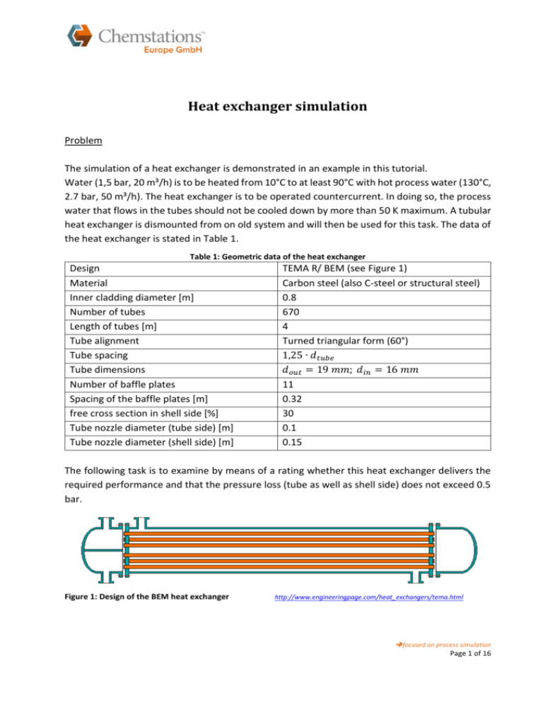
Heat exchanger simulation Problem The simulation of a heat exchanger is demonstrated in an example in this tutorial. Water (1,5 bar, 20 m³/h) is to be heated from 10°C to at least 90°C with hot process water (130°C, 2.7 bar, 50 m³/h). The heat exchanger is to be operated countercurrent. In doing so, the process water that flows in the tubes should not be cooled down by more than 50 K maximum. A tubular heat exchanger is dismounted from on old system and will then be used for this task. The data of the heat exchanger is stated in Table 1. Table 1: Geometric data of the heat exchanger Design Material Inner cladding diameter [m] Number of tubes Length of tubes [m] Tube alignment Tube spacing Tube dimensions Number of baffle plates Spacing of the baffle plates [m] free cross section in shell side [%] Tube nozzle diameter (tube side) [m] Tube nozzle diameter (shell side) [m] TEMA R/ BEM (see Figure 1) Carbon steel (also C-steel or structural steel) 0.8 670 4 Turned triangular form (60°) 1,25 ∙ 𝑑𝑡𝑢𝑏𝑒 𝑑𝑜𝑢𝑡 = 19 𝑚𝑚; 𝑑𝑖𝑛 = 16 𝑚𝑚 11 0.32 30 0.1 0.15 The following task is to examine by means of a rating whether this heat exchanger delivers the required performance and that the pressure loss (tube as well as shell side) does not exceed 0.5 bar. Figure 1: Design of the BEM heat exchanger http://www.engineeringpage.com/heat_exchangers/tema.html focused on process simulation Page 1 of 16 Solution principle and assumptions: CC-THERM is required here besides CHEMCAD Steady State to solve the problem. CC-THERM is an add-on program and comprises the rigorous simulation of heat exchangers. CHEMCAD Steady State already offers the possibility to simulate heat exchangers through a simple energy and mass balance. However, a heat transfer coefficient is not calculated, and the construction parameters are not taken into consideration. CC-THERM offers rigorous calculations of the following heat exchanger types: tubular, plate and twin tube heat exchangers and air coolers. It is possible to select between the design of a new and the rating of an existing heat exchanger. With the rating of a heat exchanger, the construction data (e.g. number of tubes, tube dimensions, number of baffle plates, etc.) of the heat exchanger are already known. This way, it is possible to check whether the required output can be achieved with the available heat exchanger for a specified substance mixture. The heat exchanger is designed and calculated in accordance with international standards: TEMA, ASME, DIN or British Standard. For the simulation at hand, the IAPWS-IF97 steam table is used as thermodynamic model for the enthalpy calculation. A thermodynamic of mixing is not required because the only available component is water. Therefore, the simplest model (ideal Raoult's law, VAP) is chosen. Table 2 summarizes the most important simulation data. Table 2: Summary of the simulation data Units Components Thermodynamics Feed streams k Unit operations Common SI Water K: VAP, H: IAPWS Hot: 1 heat exchanger; 𝑇𝐸𝑖𝑛 = 130°𝐶 2 feeds; 𝑝 = 2,7 𝑏𝑎𝑟 2 products 𝜈=0 𝑉̇𝐻𝑜𝑡 = 50 𝑚3 /ℎ Cold: 𝑇𝐸𝑖𝑛 = 10°𝐶 𝑝 = 1,5 𝑏𝑎𝑟 𝑉̇𝑐𝑜𝑙𝑑 = 20 𝑚3 /ℎ In addition, the hot flow is to have an outlet temperature in excess of 80 °C, and the cold flow an outlet temperature of 90°C. focused on process simulation Page 2 of 16 Implementation of the heat exchanger simulation in CHEMCAD First, the flow sheet is generated with CHEMCAD Steady State and the feed streams defined as stated in table Table 2 (see Figure 2). Figure 2: Flow sheet with heat exchanger The heat exchanger can be specified via different parameters in the settings window (Figure 3). Amongst other parameters, the heat exchanger surface A and the heat transfer coefficient k can be defined, from which the process data of the outlet flows is calculated afterwards. Further settings options (e.g. statement of temperature, steam content, minimum temperature difference) are also possible. In Utility Option, the required mass flow of one of the feed streams can be calculated in dependence on the other and the set parameters. The stream flow and the view of the calculated results are defined in the menu item Misc. Settings. For this simulation, the outlet temperature of the cold flow is defined. According to the task, this should be at least 90°C. A temperature of 95°C is specified. One statement is sufficient for the simulation of a simple heat exchanger. focused on process simulation Page 3 of 16 Figure 3: Settings window of the HTXR heat exchanger The simulation is started. This leads to the results shown in Figure 4. Both flows have an outlet temperature of approximately 95°C, which means that the condition stating that the hot stream should not be cooled down below 80°C is fulfilled. Figure 4: Results table of the simple heat exchanger focused on process simulation Page 4 of 16 For the rigorous simulation, CC-THERM is now called up at "Sizing: Heat Exchangers" (Figure 5). Figure 5: Path for calling up CC-THERM After selecting the tubular heat exchanger, the module first asks which feed stream is supposed to flow through the heat exchanger in the tubes first (Figure 6), and - if not already selected which heat exchanger in the flow sheet is concerned. In this example, the hot process water flows in the tubes. Figure 6: Definition of the feed stream flowing in the tubes Afterwards, CHEMCAD generates the Q-T diagram (Heat Curve, Figure 7). This is generated with 11 data points (pre-setting). It is also possible to choose between concurrent and countercurrent in the settings window "Heat Curve Parameters". focused on process simulation Page 5 of 16 Figure 7: Parameter window of the Q-T diagram The Q-T diagram already shows whether a phase change occurs inside the heat exchanger. With a pure component system, it can be expected that the temperature will no longer increase in the case of a phase change, so that the curves will become horizontal. In the examined diagram, this results in the Q-T diagram displayed in Figure 8. There is no phase change. It is also possible to read the output temperatures to be expected. The data used in the diagram originates from the previously generated heat exchanger simulation using the CHEMCAD Steady State module. Figure 8: Q-T diagram After confirming with "OK", the next window for the general settings of the heat exchanger opens automatically (Figure 9). In Calculation mode, it is possible to choose between the design or the rating case. The calculation basis for the geometric details is selected in TEMA class/standard . Different international standards are available for this purpose. The TEMA standard R (Tubular Exchanger Manufacturer’s Association Type R) is preset. focused on process simulation Page 6 of 16 The geometric layout of the heat exchanger is defined in the next step. The layout is stated using the TEMA standard. In this example, a pre-defined heat exchanger is to be rated for the given streams. This heat exchanger is based on the TEMA design. It concerns the TEMA Class R with the BEM form (Figure 1). From the pre-set process parameters, CHEMCAD automatically detects whether a phase change occurs and selects the respective calculation model in Process type. In CHEMCAD, the fouling factor is pre-set at 0.000176109 m²K/W but can be adjusted manually. Figure 9: General settings window of the CC-THERM module for tubular HE In Modeling Methods (Figure 10) the calculation methods, e.g. for laminar or turbulent flows, can be adapted if required. focused on process simulation Page 7 of 16 Figure 10: Settings window of the CC-THERM module for tubular HE, tab: Modeling methods The next settings window opens automatically after confirmation. The geometric data of the heat exchanger is defined in more detail in the following. Details of the tube bundle are entered first (Figure 11). Figure 11: Setting the tube bundle In the case of rating, all entry fields can be edited. In the case of design, the number and length of the tubes are calculated and therefore cannot be edited. CHEMCAD already contains pre-set focused on process simulation Page 8 of 16 values for a tubular heat exchanger. The dimension of the tubes is 3/4 inch. However, all values can be overwritten manually. The geometric data of the heat exchanger is entered as stated in Table 1. The pre-set values, such as the tube sheet thickness, are applied accordingly. The shell settings screen opens next (Figure 12). Besides stating the shell diameter, it is also possible to enter whether several heat exchangers are to be connected in parallel or in series. Figure 12: Shell settings The nozzles can be specified in the subsequent window (Figure 13). Pre-set values are also available here, that can be adapted manually if required. The nozzle diameter is 0.1 m for the tube side and 0.15 m for the shell side. focused on process simulation Page 9 of 16 Figure 13: Specification of the nozzles Geometric dimensions and alignments of the baffle plates can be set in the next window (Figure 14). If no values are provided, CHEMCAD calculates these with the CC-THERM calculation algorithm. There are eleven baffle plates in the stated heat exchanger, which cover 70% of the cross section. Therefore, the free cross section in the shell is 30%. CHEMCAD calculates the spacing of the baffle plates automatically. Figure 14: Settings of the baffle plates focused on process simulation Page 10 of 16 In the following windows that appear, the geometric clearances inside the heat exchanger (Clearance Specifications: Figure 15) are defined, the material of the heat exchanger is specified (Material Specifications: Figure 16), and in Miscellaneous Specifications (Figure 17) some additional settings, e.g. statement of the heat output to be achieved can be entered. No further settings are made in the next windows. The heat exchanger consists of carbon steel, so that no changes are made in Figure 16 . All other pre-set values are applied. The geometric data, e.g. clearances inside the heat exchanger, has little influence on the simulation but is decisive for the design of the heat exchanger. It is not necessarily required for the simulation to enter this data. Figure 15: Settings window for the geometric spaces in the heat exchanger focused on process simulation Page 11 of 16 Figure 16: Settings window for the material selection Figure 17: Settings window for other settings Once all settings have been completed, the main menu of the tubular heat exchanger is displayed in CC-THERM (Figure 18). focused on process simulation Page 12 of 16 Figure 18: Main menu of the tubular heat exchanger The rigorous simulation of the heat exchanger with the previously entered data is performed with the command Calculate. The results of the calculation can be viewed in View Results. It is also possible to have the results exported to Excel or as a text file. The desired report section can be selected in Select Reports and afterwards generated with Generate Reports (Figure 19). Figure 19: Selection of the report sections focused on process simulation Page 13 of 16 To enter the CC-THERM calculation in the CHEMCAD simulation, the main menu is now closed via Exit. The changes are saved. Now the settings window of the previously generated heat exchanger is opened with a double-click. In Simulation mode, switch to the option 1 shell & tube simulation. The construction data for the heat exchanger simulation previously entered in CCTHERM is now used (Figure 20). The simulation is started again. Figure 20: Switching to the CC-THERM simulation Assessment of the simulation results The results table is updated after the simulation (Figure 22). It becomes evident that the outlet temperature of the hot stream is now cooled down to approximately 85°C (previously: 95°C). The outlet temperature of the cold stream is now 110°C. The heat exchanger thus delivers the required performance. The pressure loss, amongst other parameters, can be derived from the results of the heat exchanger (Figure 21). The pressure loss is less than 0.5 bar, on both the tube and the shell sides. These requirements are therefore fulfilled. However, approximately 2% of the water now evaporates on the cold side due to the higher outlet temperature and the pressure loss. As this not desired, further measures (e.g. increasing the pressure on the cold side) are required to be able to use the heat exchanger for the desired task. Figure 21: Results table of the heat exchanger Besides this results output in the flow sheet, it is possible to have a summary of the CC-THERM results issued, e.g. as a TEMA datasheet (see Figure 19). focused on process simulation Page 14 of 16 Figure 22: Results table after the CC-THERM simulation Optimization approaches It is also possible to design a heat exchanger in CHEMCAD. It is not necessary to know any construction data for this purpose. Merely the desired heat output or the desired outlet temperatures must be specified. The construction and the geometric data is calculated in design mode. Another optimization approach would be to investigate to what extent the heat exchange deteriorates if the tubes inside the heat exchanger become clogged and must be welded shut. Closing off the tubes would be one possibility to prevent the evaporation on the cold side in the above example by reducing the heat exchanger surface. Another question would be how many tubes may fail at most while still achieving the required performance. The simulation with a reduced number of tubes can be performed and the influence on the heat output examined with CC-THERM. In addition, the sensitivity analysis and SQP optimization tools available in CHEMCAD can be used to examine various parameters and scenarios. In the field of heat recovery, a heat exchanger with bypass construction is frequently used. If heat recovery is not possible in the summer, the hot waste gas, for example, is directed past the heat exchanger via the bypass. A bypass can be simulated in CHEMCAD e.g. with the help of controllers so that different operation scenarios can be quickly examined. CC-THERM can be used for other types of heat exchangers (plate and twin tube heat exchangers and air coolers) in the same way. These procedures are contained in further tutorials. focused on process simulation Page 15 of 16 Are you interested in further tutorials, seminars or other solutions with CHEMCAD? Then please contact us: Mail: support@chemstations.eu Phone: +49 (0)30 20 200 600 www.chemstations.eu Author: Lisa Weise focused on process simulation Page 16 of 16
