a software suite with total synergy
advertisement
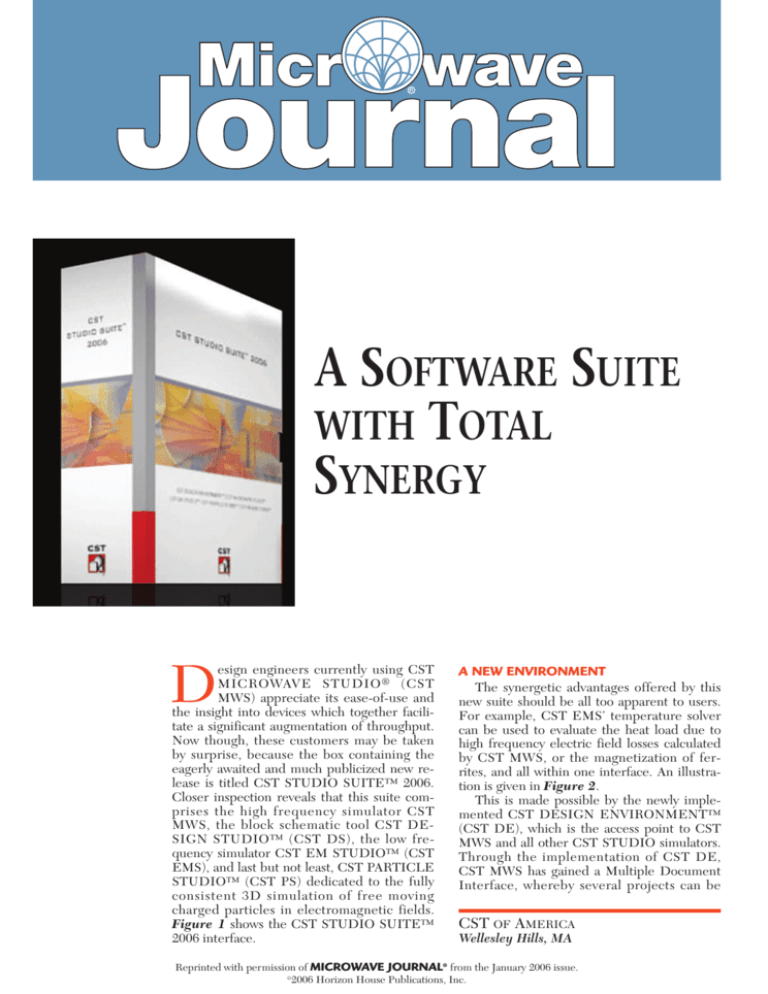
A SOFTWARE SUITE WITH TOTAL SYNERGY D esign engineers currently using CST MICROWAVE STUDIO ® (CST MWS) appreciate its ease-of-use and the insight into devices which together facilitate a significant augmentation of throughput. Now though, these customers may be taken by surprise, because the box containing the eagerly awaited and much publicized new release is titled CST STUDIO SUITE™ 2006. Closer inspection reveals that this suite comprises the high frequency simulator CST MWS, the block schematic tool CST DESIGN STUDIO™ (CST DS), the low frequency simulator CST EM STUDIO™ (CST EMS), and last but not least, CST PARTICLE STUDIO™ (CST PS) dedicated to the fully consistent 3D simulation of free moving charged particles in electromagnetic fields. Figure 1 shows the CST STUDIO SUITE™ 2006 interface. A NEW ENVIRONMENT The synergetic advantages offered by this new suite should be all too apparent to users. For example, CST EMS’ temperature solver can be used to evaluate the heat load due to high frequency electric field losses calculated by CST MWS, or the magnetization of ferrites, and all within one interface. An illustration is given in Figure 2. This is made possible by the newly implemented CST DESIGN ENVIRONMENT™ (CST DE), which is the access point to CST MWS and all other CST STUDIO simulators. Through the implementation of CST DE, CST MWS has gained a Multiple Document Interface, whereby several projects can be CST OF AMERICA Wellesley Hills, MA Reprinted with permission of MICROWAVE JOURNAL® from the January 2006 issue. © 2006 Horizon House Publications, Inc. P RODUCT F EATURE from other simulation methods) is the key strength of CST DS. It employs sophisticated caching and interpolation schemes to speed up parameter studies and optimizations. It is strongly focused on improving 3D EM simulation performance, and takes some users one step along the path towards circuit simulation. ▲ Fig. 1 CST STUDIO SUITE™ 2006 interface. opened simultaneously. Therefore, the user can easily switch between projects, compare and copy/paste results. CST DE also allows switching to the VBA editor. MODELING AND INTEROPERABILITY The success of CST MWS has always been closely related to having introduced an easy-to-use interface to the 3D EM field simulation community. It allows fast modeling of complex structures, promoting design intent capture and implicit (together with explicit and even subsequent) parameterization of geometrical models. A wide range of interfaces to mechanical CAD tool formats is available too, and the imported CAD data can be parameterized and made accessible to optimization. Entirely new are the interfaces to VDA-FS and Mecadtron formats. The interface to Cadence Allegro has undergone a complete rework, resulting in improved front-end performance. Figure 3 shows a structure imported from Cadence. The interface also now features a stack-up editor. This represents a first step towards interfacing with other EDA-vendors like Mentor Graphics or Zuken. Planar imports can be easily extended by an automated JEDEC compliant bondwire creation and users can simply switch between an idealized and a solid model representation. In addition to CAD interfaces, current distributions, from SimLab PCBMod, for example, can now be loaded as sources for EMC/EMI studies. SCHEMATIC VIEW Upon opening a CST MWS project, the user will notice that an additional CST DS view is available. Even with the basic license, RLC elements as well as a few other components can be attached to the ports, and S-parameter simulations can be performed. A full CST DS license would enable access to a far wider range of circuit elements. The composition of larger systems out of small 3D CST MWS models (but also models originating EM/CIRCUIT CO-SIMULATION A major concern in today’s high frequency design of PCBs and packages is signal integrity and radiated emission. With Agilent’s ADS 2005A and CST MWS 2006, the companies now present an improved EM/circuit co-simulation scheme that enables the complete integration of 3D models in the ADS workflow. Any CST MWS model can be made available for co-simulation as a library element. The user can specify the parameters to be made accessible in the ADS circuit model. If used in tuning or optimization, intermediate results can be obtained by interpolating existing results. Whenever necessary (or wanted) a full 3D simulation can be launched directly from the ADS schematic. Each simulation result is added to the library element cache, thus continuously increasing its value. SOLVER TECHNOLOGY CST MWS is said to be the only commercial 3D simulator to offer time domain and frequency domain on Cartesian and tetrahedral grids, accessible through one easy-to-use interface. The flagship module, the transient solver, is the first choice for electrically large, complex or broadband structures. These capabilities have been extended by the implementation of 64-bit technology. Besides the user interface, the company’s proprietary Perfect Boundary Approximation (PBA) technique can be seen as the other foundation stone on which its success has been built. Its implementation has been shown to signifiK 342 340 336 333 330 327 324 321 317 314 311 308 305 300 Type Maximum-3D Frequency ▲ Fig. 2 = Temperature = 342.169 K at -3.79289/-3.61429/0.25 =0 Temperature distribution of an IC cooling element. P RODUCT F EATURE cantly improve the efficiency of time domain methods through accurate geometrical structure representation. The transient solver now takes advantage of a new meshing algorithm. The robust mesher shows excellent performance particularly for complex, imported structures. Further improvements include the definition of frequency dependent material through tables. This also applies to voxel imports, thus enabling highly accurate broadband EM simulation of biological tissues. The main focus of development for version 2006 has been the tetrahedral frequency domain (FD) solver. This complements the time domain solver, and shows its particular strengths if structures are electrically small or periodic. Particularly interesting is the ability to mesh the true surface of the structure without having to pre-segment rounded objects. Users can choose between an iterative solver, where memory requirements scale better with problem size, and a direct solver, which performs efficiently on multi-port structures, since the simulation time is not strongly dependent on the number of ports. For periodic structures like phased arrays, PBGs, FSS and meta-materials the FD solver features a powerful algorithm that automatically sets up the unit cell for easy scan angle study. This is illustrated in Figure 4. Also, an adaptive frequency sweep speeds up broadband investigations by reducing the number of simulations necessary to achieve the desired accuracy. There are now two dedicated solvers for resonant high Q structures like filters. The first is based on a model order reduction (MOR) scheme, and calculates S-parameters directly and extremely quickly but without calculating fields. If the fields are required, the modal analysis approach can be applied. The Eigenmode solver that solves closed or periodic structures, taking losses into consideration, completes the palette of solvers. PERFORMANCE AND AUTOMATION Users of CST MWS can take advantage of multiple processors in several ways — by using the parallel processing functionality, by which one simulation can use several CPUs on one mainboard, or through the distributed computing scheme, which can also utilize other computers in a network. For parameter studies and optimizations, runs with different parameter sets are allocated from, and results are collected and evaluated in one central front-end. New parameter sets for the next run of simulations are set up and distributed again. This scheme has been significantly improved in terms of network traffic, error tolerance and stability. VBA macro language is also implemented. This, together with the COM/DCOM interface, makes the software accessible through other software packages, for example, if a user wants to im▲ Fig. 3 Structure imported from Cadence. plement his own evaluation or optimization schemes. Multi-run simulations, like monostatic RCS calculation, can be automated easily using either pre or user defined macros. POST PROCESSING New post-processing features in version 2006 include the calculation of far fields over lossy ground, thus enabling the simulation of outdoor test ranges, a new broadband SPICE extraction scheme and average plots used for MRI applications. The access to result data is facilitated through a sophisticated automatic post-processing scheme. Arbitrary goal (a) (b) (c) ▲ Fig. 4 Creation of a unit cell; (a) single element, (b) automatic set-up of the unit cell and (c) the Floquet mode port boundary, calculation domain. P RODUCT F EATURE functions can be derived for the two implemented automatic optimizers from a large, user extendable number of evaluations. For the visualization of parameter dependant result data, users can now employ tuning sliders. CONCLUSION CST MWS version 2006 is a versatile simulator that offers users significantly increased value through its integration in CST STUDIO SUITE,™ the new multiple document interface and numerous improvements in all areas. The company uniquely enables access to time do- main and frequency domain, on Cartesian or tetrahedral meshes through one interface, and its application range now spans from static to optical frequencies. CST of America, Wellesley Hills, MA (781) 416-2782; CST GmbH, Darmstadt, Germany, + 49 (0) 6151 73030, www.cst.com.
