FACTORIZATION FOR ANALOG-TO-DIGITAL MATRIX
advertisement

FACTORIZATION FOR ANALOG-TO-DIGITAL MATRIX MULTIPLICATION
Edward H. Lee? , Madeleine Udell† , and S. Simon Wong?
?
†
Department of Electrical Engineering, Stanford University
Institute for Computational and Mathematical Engineering, Stanford University
ABSTRACT
We present matrix factorization as an enabling technique for
analog-to-digital matrix multiplication (AD-MM). We show
that factorization in the analog domain increases the total precision of AD-MM in precision-limited analog multiplication,
reduces the number of analog-to-digital (A/D) conversions
needed for overcomplete matrices, and avoids unneeded computations in the digital domain. Finally, we present a factorization algorithm using alternating convex relaxation.
Index Terms— Analog-to-digital conversion, matrix factorization, compressed sensing, analog-to-information.
1. INTRODUCTION
Analog-to-digital matrix multiplication (AD-MM) is a common task in modern sensing and communication systems.
AD-MM digitizes an analog signal and multiplies the resulting data by a matrix. For example, AD-MM is used
in cameras to compress digital data using transform coding
and quantization [1]. Furthermore, many analog signals are
known to have a sparse representation in some basis, which
presents an opportunity to reduce the number of A/D conversions and the output (digital) data rate of AD-MM.
Many recent papers [2–10] have explored using analog
matrix multiplication to alleviate A/D requirements for ADMM. For example, hardware implementations of compressed
sensing (CS) known as Analog-to-Information Converters
(AIC) multiply in the analog domain a signal x, which is
low-dimensional in some basis Ψ ∈ Rn×n , by a matrix
A ∈ Rm×n that is incoherent with Ψ [11, 12]. The incoherence requirement places restrictions on allowable matrices A. In practice, only Bernoulli and Hadamard matrices
(A ∈ {0, 1}m×n ) are used; other allowable matrices with
real-valued entries (e.g., random Gaussian and partial Fourier
matrices [3,13]) are usually not used due to the high precision
requirements of analog hardware.
The practical limitations on the precision and size of the
matrix operation not only affect AICs, but also affect other
This work was supported by the Texas Instruments Stanford Graduate
Fellowship, the Gerald J. Lieberman Fellowship, the Gabilan Stanford Graduate Fellowship, and the National Science Foundation Graduate Research
Fellowship under Grant No. DGE-1147470.
forms of analog matrix multiplication. For example, many
recent papers [5–10] propose applying the discrete Fourier
transform (DFT) in the analog domain for use in software defined radios. The analog DFT enables RF channelization [7]
in order to relax the high RF sampling requirements from the
signal-to-noise ratio (SNR) requirements, reducing the overall A/D power [14]. However, in practice, analog DFT implementations are restricted to small (e.g., n = 16) matrices due
to the large precision required.
1.1. Contributions.
In this paper, we offer factorization as a technique to increase
the total precision of AD-MM while tolerating lower analog
multiplication precision. We also show that analog AD-MM
reduces the number of A/D conversions and can lower overall
energy compared to digital (conventional) AD-MM for overcomplete matrices.
This paper is structured as follows. In §2, we present the
motivations for matrix factorization. In §3, we discuss four
applications of analog AD-MM using factorization. In §4, we
present an algorithm to factor large matrices and show that
it can efficiently compute a good factorization requiring only
modest analog precision.
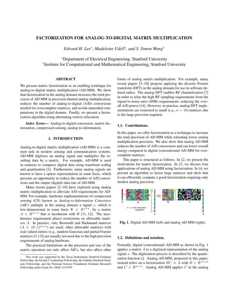
Fig. 1. Digital AD-MM (left) and analog AD-MM (right).
1.2. Definitions and notation.
Formally, digital (conventional) AD-MM as shown in Fig. 1
applies a matrix A to a digitized representation of the analog
signal x. The digitization process is described by the quantization function Q. Analog AD-MM, proposed in this paper,
instead relies on a factorization BC ≈ A with B ∈ Rm×m
and C ∈ Rm×n . Analog AD-MM applies C in the analog
domain to the analog data x ∈ Rn , quantizes the result, and
finally applies B in the digital domain to produce the output z.
Our goal is to design B and C such that BQ(Cx) ≈ AQ(x).
Throughout this paper, we restrict our attention to square matrices B, although extensions to rectangular B are possible,
and usually consider the overcomplete case m < n.
2. MATRIX FACTORIZATION: MOTIVATIONS
In digital matrix multiplication, an increase in precision (or
resolution) necessitates an increase in the number of digital
control gates, size of memory, and interconnects, all of which
increase the energy of a multiply-and-accumulate (MAC) operation [15]. Energy also increases with precision in analog
matrix multiplication. A prototype analog multiplier (Fig. 2)
illustrates how each voltage xj is sampled on the capacitor
array connected to the signal path at time j to form a charge
proportional to the total capacitance of the array. We let cij
be the constant of proportionality. This sampling operation is
performed for each j = 1 : n and accumulated together in
the analog charge domain to form yi = Σnj=1 cij xj . Analog
charge domain multiplication is a practical approach for analog MAC, although many other approaches and variants are
possible [10, 16]. Nonetheless, with any of these approaches,
an increase in precision of the analog matrix C requires an increase in the number of different analog multiplier elements
(e.g., capacitors in Fig. 2), for the roughly the same reasons
as in the digital case. Therefore, energy grows with precision
just as it does in digital domain matrix multiplication.
Fig. 2. Example of an analog charge-domain multiplier with
12
shown) with precision
binary-weighted encoding (cij = 1024
10
NC = 10 bits (2 different multiplier values).
Factorization can relax the hardware requirements imposed by a need for high precision. Formally, to find a good
factorization, we solve for B and C in
minimize ||A − BC||F
subject to C ∈ ΩC
B ∈ ΩB ,
(1)
where C (B) is constrained to take on values in an integer
set ΩC (ΩB ). For example, Fig. 2 gives an example using
binary-weighted encoding, i.e.,
cij =
cmax
y ,
2NC ij
−2NC ≤ yij ≤ 2NC ,
yij ∈ Z,
for i = 1, ..., n and j = 1, ..., m, where NC is the multiplier precision. The constraint sets (ΩB , ΩC ) can also enforce
non-negativity and other constraints to capture the hardware
limitations of analog multiplication.
How much precision do we require in C? The answer
depends on the application — for example, a coarse multiplication where C = Q(A) at the 2 bit level is good enough
for detection (see §4) while 10 bits may be required to meet
stringent SNR requirements.
Recall that the dimensionality of the digital output space
is size m, while the dimensionality of the analog input space
is size n, where m < n. Thus analog AD-MM requires only
m A/D conversions, a significant savings over the n A/D conversions required by a digital AD-MM system. Analog ADMM also requires a digital computation (i.e., multiplication
by B) of size m2 , instead of nm for digital AD-MM, but has
the added overhead of the analog multiplication by C of size
nm.
Furthermore, pruning (eliminating outputs (Cx)j ≈ 0)
also reduces the number of digital MACs required. If we can
detect (Cx)j ≈ 0, then we need not multiply it by the j-th
row of B. For example, if |(Cx)j | ≤ δ for all j = 1, . . . , m
and δ is an application-specific pruning threshold, then multiplication by B need not be performed (see §??).
Thus, compared to digital AD-MM, analog AD-MM requires fewer A/D conversions and fewer digital MACs, but
incurs the extra overhead of the analog multiplication Cx. To
first order, the circuit-independent energy estimates for digital
(Ed ) and analog (Ea ) AD-MM are
Ed
' mnEd-op + nEA/D
Ea
' mnEa-op + mEA/D + (γm)2 Ed-op ,
where Ed-op is the energy cost per digital MAC operation
(Joule/op), EA/D is the cost per A/D conversion, Ea-op is the
cost per analog MAC operation, and γ ∈ [0, 1] is the pruning factor. We assume here that the A/D quantizes the analog
signal to the same precision for both architectures. (All three
energy costs depend strongly on the precision.)
The first-order estimates show that increasing n increases
both the digital MAC and the A/D costs in digital AD-MM
but increases only the analog MAC cost in analog AD-MM.
Furthermore, [7, 8] report that Ea-op < Ed-op , which makes
analog AD-MM attractive from an energy perspective as well.
For example, the charge-domain FFT proposed in [7] achieves
an energy per analog FFT operation that is 130 times lower
than its digital equivalent, at similar SNR levels.
3. EXAMPLES
Using four examples, we show that lowering the precision in
B and C need not decrease the fidelity of the output z.
3.1. Factorization for precision-limited C
As a first example (Fig. 3), we factor a truncated discrete cosine transform (DCT) matrix A ∈ R50×120 , keeping the 50
basis vectors (rows) of lowest frequency, and constrain the
factor C to have binary-weighted elements with precisions
NC = 10, NC = 6, and NC = 4 bits. The factorizations
decrease in quality at lower precision, achieving MSEs of
4.8 × 10⁻⁵ , 6.6 × 10⁻⁴ , and 1.3 × 10⁻³ for NC = 10, 6,
and 4 respectively.
arithmetic. The data A ∈ R20×200 is generated by selecting entries uniformly from [−1, 1]. The desired output is
ztrue = Ax where x is a 10-bit FP i.i.d. Gaussian random
vector. To factor A into B and C, we solve Prob. 1 with
the constraint that ||B||∞ ≤ 1. Define zA = QNA (A)x and
zBC = QNB (B)QNC (C)x, where QN denotes quantization
to N bits in FP, and all MAC operations are performed in FP
arithmetic. We measure output error on output z as the average of the loss L(z) = ||z − ztrue ||2 over 1000 realizations of
the input x.
Fig. 5 shows E[L(zA )] and E[L(zBC )] as we vary the
precision NB of B while fixing the precision of A, C, and
Cx. We achieve similar expected loss using factored AD-MM
with NB = 5 and NC = 4 or using digital AD-MM with
NA = 5. For higher NB , FP factored AD-MM approaches
the performance of infinite precision factored AD-MM. We
can further decrease the expected loss by finding a better factorization of A into low precision factors; we return to this
question in §4.
2.5
zBC=B(Cx): C[4b], B[NB], z=B(Cx)[19b]
E[L(z)]
2
z=BCx (no restrictions on precision)
zA=Ax: A[5b], z=Ax[19b]
1.5
1
0.5
0
Fig. 3. Factorization results on the truncated DCT matrix.
3.2. Image Reconstruction
As a second example (Fig. 4), we factor a truncated DCT matrix A ∈ R16×64 with NC = 10 bit for an application in image reconstruction. The resulting matrix BC is used to reconstruct the image for each color channel (RGB) independently.
The reconstrunction shows little loss in fidelity, despite a 4:1
compression ratio. The peak SNR decreases from 28.3 dB
(original) to 26.7 dB (reconstruction).
Fig. 4. Reconstruction of an image on 8 × 8 patches.
3.3. Factorization for precision-limited B and C
As our third example, we show that factorization allows us
to use lower precision in our intermediate MAC operations
while maintaining approximately the same output error in z.
In Fig. 5, we examine the effect of bounded precision in A,
B and C on fidelity of the output, using fixed-point (FP)
1
2
3
4
5
NB (bits)
6
7
8
9
Fig. 5. Expected output error for FP factored AD-MM and FP
digital AD-MM. Here, A[NA ] denotes A quantized to precision NA in FP.
3.4. Detection and estimation
Many sensing applications (e.g., radar) require the ability
to actively detect a signal’s presence and the ability to estimate signal features. If the detection accuracy is robust to
decreased precision, low precision sensing can save energy
while reliably detecting the signal. However, high precision
may be necessary to estimate signal features once the signal
is detected.
As an example of a detection-estimation problem, consider a generalized likelihood ratio test (GLRT) [17]. The task
is to classify whether the signal is present or not, and to estimate the (unknown) time of arrival (s∆t ). Let the observation
vector be x ∈ Rn , the signal be s ∈ Rn , and the noise be w ∼
N (0, σ 2 I) (Fig. 6 (b)). The GLRT (with threshold η) rejects
the null hypothesis H0 (no signal) in favor of H1 (signal) if
p(x;∆t̂,H1 )
p(x;H0 ) > η for all ∆t̂. The maximum likelihood estimate
of the time of arrival (ToA) is ∆t̂ = arg maxj aTj x, where aTj
is a row vector containing a time-shifted version of s. These
row vectors are collected in the matrix A (see Fig. 6 (a)). For
detection, we let C be the positive part of QNC (A), i.e., the
matrix A quantized to NC bits. We force C to be nonnegative,
since an analog multiplier in practice generally requires additional control logic to encode negative values. Then, for ToA
estimation, we set B = argminB∈ΩB ||A − BC||F , where
ΩB = Rm×m .
We show in Fig. 6(c) only a modest decrease in detection
accuracy for a 1-bit, nonnegative C at a given SNR compared
to using full precision A. Furthermore, using the backend
matrix B significantly increases the time of arrival (ToA) estimation accuracy, conditioned on detection of the signal (see
Fig. 6(d)). For example, with an SNR = −7.8 dB, we see an
increase from 74% to 91% ToA estimation. Thus, for this particular application of AD-MM, reducing precision is practical
since it lowers the analog AD-MM complexity while preserving detection performance.
Input Waveform (SNR = −6.6 dB)
0.08
0.06
0.04
0.02
0
−0.02
resulting matrix with N bit precision. We then use alternating minimization to find an approximate solution for the full
problem:
1: repeat
2:
B (k) ← QNB argminB∈conv(ΩB ) ||A − BC||F
3:
C (k) ← QNC argminC∈conv(ΩC ) ||A − BC||F
4:
k+1 ← ||A − B (k) C (k) ||F
5: until converged
We compute the approximation error = ||A−BC||F for
factorizations of 50 randomly initialized (RI) matrices, where
C is constrained to lie in a nonnegative, FP set. The final
distribution of for different precisions shown in Fig. 7(a),
and indicates that converges to a compact minimum at 10
bit precision after just a few iterations. However, for smaller
precisions, the average is significantly worse (see Fig. 7(b)).
Greedy initialization (GI) overcomes this problem. GI
uses the locally optimal matrices C (k−1) found at higher precisions NC + 1 and NB + 1 to initialize C in the alternating
minimization to initialize the search for a new factorization
with precisions NC and NB . Fig. 7(b) shows that the GI performs substantially better than RI at low precision.
−0.04
Signal s
−0.06
−0.08
0
50
100
150
Factor (100 x 500, Non−negative)
N = 10b (Non−negative Factor, 100 x 500)
Measured x = s + w
7
200
c
9
8
6
Time i
1
(b)
Time of Arrival Accuracy
5
4
3
3
1
0.95
4
ε
Signal Detection Accuracy
6
Count
(a)
2
2
0.9
Accuracy
0.85
AUC
0.8
0.75
0.7
0.8
1
0.6
0
0.72
Matrix A used
0.6
C (1b)
0.2
−10
−5
Input SNR [dB]
(c)
0
0.76
0.78
0.8
Frobenius Norm Error
0.82
0.84
5
6
7
8
9
10
NC (bits)
(b)
BC
A (orig.)
−15
0
0.74
C=Q(A), 2b + Nonneg.
C (1b + nonneg.)
0.55
1
(a)
0.4
0.65
0.5
−20
Random Initialized (RI)
Greedy Initialization (GI)
7
5
5
−20
−10
0
Input SNR [dB]
10
(d)
Fig. 6. (a) Factorization for A where C is constrained to be
nonnegative, with 2 bit precision. (b) The input waveform. (c)
Area Under the Curve (AUC) found from Receiver Operating
Characteristic curves. (d) ToA accuracy.
4. COMPUTING THE FACTORIZATION
For most applications with stationary signal statistics, factorization need only be performed once, but must be done
well. Unfortunately, the factorization problem in Eq. 1 is not
convex, due to 1) the non-convex constraints C ∈ ΩC and
B ∈ ΩB , and 2) the product of variables BC. To find an
approximate solution for one variable holding the other fixed,
we use a relax-and-round heuristic: minimize over the convex hull of the feasible set (i.e., conv(Ω)), and quantize the
Fig. 7. (a) Histogram using the RI factorization procedure.
(b) for different precisions NC using RI and GI.
5. CONCLUSION
Factorization is an enabling technique for analog AD-MM
that increases its advantages over (conventional) digital ADMM. Factorization can increase the total precision of analog AD-MM even with lower analog multiplication precision.
Examples show that analog AD-MM performs well and that a
good factorization requiring only modest analog precision can
be efficiently computed. The authors are currently working to
implement analog AD-MM in hardware.
6. ACKNOWLEDGEMENTS
We thank Boris Murmann, Daniel Bankman, Chris Young,
Doug Adams, Niki Hammler, Thomas Lipp, Stephen Boyd,
and Abbas El Gamal for their helpful comments.
7. REFERENCES
[1] A. El Gamal and H. Eltoukhy, “CMOS image sensors,”
IEEE Circuits and Devices Magazine, vol. 21, no. 3, pp.
6–20, May 2005.
[12] O. Abari, F. Lim, F. Chen, and V. Stojanovic,
“Why Analog-to-Information Converters suffer in highbandwidth sparse signal applications,” IEEE Transactions on Circuits and Systems I: Regular Papers, vol.
60, no. 9, pp. 2273–2284, 2013.
[2] D. Adams, C. S. Park, Y. C. Eldar, and B. Murmann,
“Towards an integrated circuit design of a Compressed
Sampling wireless receiver,” in 2012 IEEE International
Conference on Acoustics, Speech and Signal Processing
(ICASSP), March 2012, pp. 5305–5308.
[13] W. Yin, S. Morgan, J. Yang, and Y. Zhang, “Practical
compressive sensing with Toeplitz and circulant matrices,” in Visual Communications and Image Processing
2010. International Society for Optics and Photonics,
2010, pp. 77440K–77440K.
[3] M. Herman and T. Strohmer, “Compressed sensing
radar,” in IEEE Radar Conference, 2008. RADAR ’08.,
May 2008, pp. 1–6.
[14] B. Murmann, “ADC Performance Survey 1997-2014,”
[Online]. Available:
http://web.stanford.
edu/˜murmann/adcsurvey.html.
[4] Y. Oike and A. El Gamal, “CMOS Image Sensor with
Per-Column Σ∆ ADC and Programmable Compressed
Sensing,” IEEE Journal of Solid-State Circuits, vol. 48,
no. 1, pp. 318–328, Jan 2013.
[15] S. Galal and M. Horowitz, “Energy-Efficient FloatingPoint Unit Design,” IEEE Transactions on Computers,
vol. 60, no. 7, pp. 913–922, July 2011.
[5] A. A. Abidi, “The Path to the Software-Defined Radio
Receiver,” IEEE Journal of Solid-State Circuits, vol. 42,
no. 5, pp. 954–966, May 2007.
[6] B. Sadhu, M. Sturm, B. M. Sadler, and R. Harjani,
“A 5GS/s 12.2pJ/conv. analog charge-domain FFT for
a software defined radio receiver front-end in 65nm
CMOS,” in 2012 IEEE Radio Frequency Integrated Circuits Symposium (RFIC), June 2012, pp. 39–42.
[7] B. Sadhu, M. Sturm, B. M. Sadler, and R. Harjani,
“Analysis and Design of a 5 GS/s Analog ChargeDomain FFT for an SDR Front-End in 65 nm CMOS,”
IEEE Journal of Solid-State Circuits, vol. 48, no. 5, pp.
1199–1211, May 2013.
[8] Y-W. Lin, H-Y. Liu, and C-Y. Lee, “A 1-GS/s FFT/IFFT
processor for UWB applications,” IEEE Journal of
Solid-State Circuits, vol. 40, no. 8, pp. 1726–1735, Aug
2005.
[9] M. Lehne and S. Raman, “A 0.13µm 1-GS/s CMOS
Discrete-Time FFT processor for Ultra-Wideband
OFDM Wireless Receivers,” IEEE Transactions on Microwave Theory and Techniques, vol. 59, no. 6, pp.
1639–1650, June 2011.
[10] F. Rivet, Y. Deval, J. Begueret, D. Dallet, P. Cathelin,
and D. Belot, “The Experimental Demonstration of
a SASP-Based Full Software Radio Receiver,” IEEE
Journal of Solid-State Circuits, vol. 45, no. 5, pp. 979–
988, May 2010.
[11] S. Kirolos, J. Laska, M. Wakin, M. Duarte, D. Baron,
T. Ragheb, Y. Massoud, and R. Baraniuk, “Analog-toInformation Conversion via Random Demodulation,” in
2006 IEEE Dallas/CAS Workshop on Design, Applications, Integration and Software. IEEE, 2006, pp. 71–74.
[16] W. Xiong, U. Zschieschang, H. Klauk, and B. Murmann, “A 3V 6b successive-approximation ADC using
complementary organic thin-film transistors on glass,”
in 2010 IEEE International Solid-State Circuits Conference Digest of Technical Papers (ISSCC), Feb 2010, pp.
134–135.
[17] S. M. Kay, Fundamentals of Statistical Signal Processing: Estimation Theory, Prentice-Hall, Inc., Upper Saddle River, NJ, USA, 1993.


