Chapter7 - Department of Mechanical Engineering UPRM
advertisement
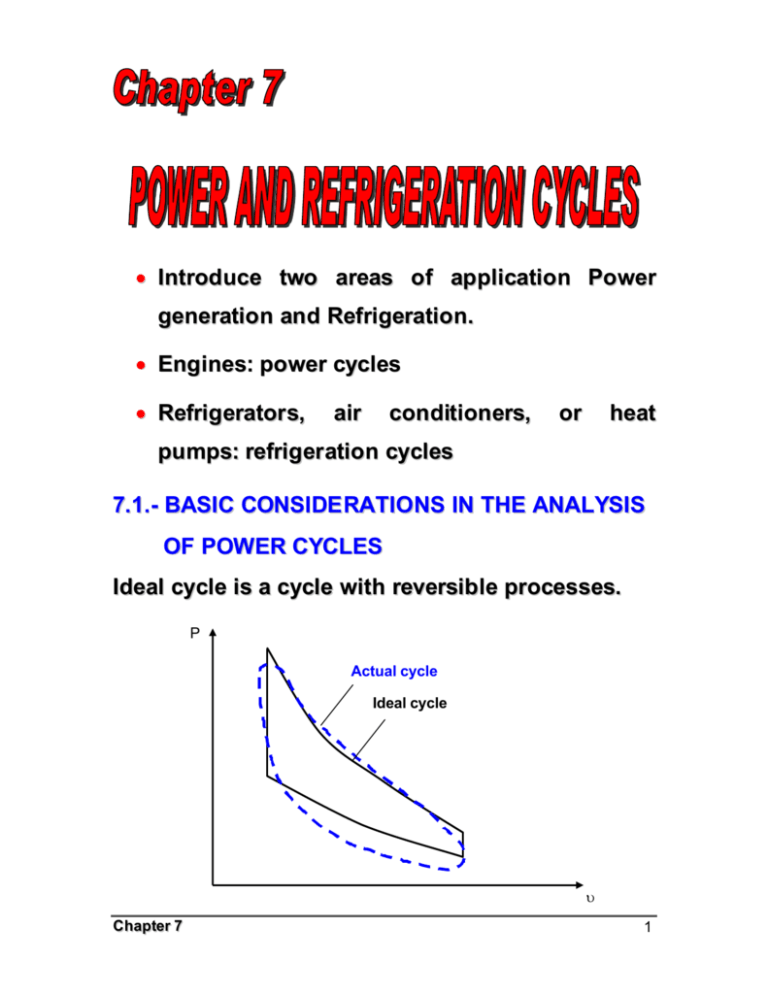
• Introduce two areas of application Power generation and Refrigeration. • Engines: power cycles • Refrigerators, air conditioners, or heat pumps: refrigeration cycles 7.1.- BASIC CONSIDE RATIONS IN THE ANALYSIS OF POWER CYCLES Ideal cycle is a cycle with reversible processes. P Actual cycle Ideal cycle υ Chapter 7 1 The idealizations and simplifications commonly employed in the analysis of power cycles can be summarized as follows: 1. The cycle does not involve any friction. Therefore, th e working fluid does not experience any pressure drop as it flows in pipes or devices such as heat exchangers. 2. All expansion and compression processes take place in a quasi-equilibrium manner. 3. The pipes connecting th e various components of a system are well insulated, and heat transfer through them is negligible. P T 3 2 3 2 w net 1 w net 4 1 4 υ Chapter 7 s 2 7.2.- THE CARNOT CYCLE AND ITS VALUE IN ENGINEERING The Carnot cycle, this was introduced and discussed in Chap. 5, is composed of four totally reversible processes: isothermal heat addition, isentropic expansion, isothermal heat rejection, and isentropic compression. The P- υ and T-s diagrams of a Carnot cycle are replotted P T 1 qin TH 2 TH= const. Isentropic Wnet, 2 3 Isentropic Isentropic 4 qin TL 1 Isentropic qout 4 TL= const. qout 3 s υ The Carnot cycle can be executed in a closed system (a piston cylinder device) or a steady-flow system (utilizing tw o turbines and two compressor), and either a gas or vapor can be Chapter 7 υ 3 utilized as the working fluid. The Carnot cycle is the most efficient cycle that can be executed between a thermal energy source at temperature TH and a sink at temperature TL, and thermal efficiency is expressed as TL η th = 1 − TH A steady-flow Carnot engine Chapter 7 4 7.3.- AIR-STANDARD ASSUM PTIONS In a gas power cycles, the working fluid remains a gas throughout the entire cycle. Spark-ignition automobile engines, diesel engines, and convectional gas turbine are familiar examples of devices that operate on gas cycle. That is, they are INTERNAL COM BUSTION ENGINES. The actual gas power cycl es are rather complex. To reduce the analysis to a manageable level, we utilize the following approximations, commonly known as the AIR-STANDARD ASSUM PTIONS. 1. The working fluid is air that continuously circulates in a closed loop and always behaves as an ideal gas. 2. All the processes that make up the cycle are internally reversible. 3. The combustion process is replaced by a heat addition process from an external source. Chapter 7 5 4. The exhaust process is replaced by a heat rejection process that restores the working fluid to its initial state. AIR Combustion Chamber COMBUSTION PRODUCTS FUEL Actual AIR Heating section AIR Ideal Another assumption that is often utilized to simplify the analysis even more is that the air has constant specific heat whose values are determined at room temperature (25ºC, or 77ºF). When this assumption is utilized, the air-standard assumption are called the COLD-AIR-STANDARD Chapter 7 6 ASSUM PTIONS. A cycle for which the air-standard assumptions are applicable is frequently referred to as an AIR-STANDARD CYCLE. 7.4.- BRIEF OVERVIEW OF RECIPROCATING ENGINES Despite its simplicity, the reciprocating engine (basically a piston-cylinder device) is one of the rare inventions that has proved to be very versatile and to have a wide range of applications. It is the powerhouse of vast majority of automobiles, trucks, light aircraft, ships, and electric power generators, as well as many other devices. The basic components of a reciprocating engine are show here: Chapter 7 7 Nomenclatur e for reciprocating engines The piston reciprocates in the cylinder between two fixed positions called the TOP DEAD CENTER (TDC)-the position of the piston when it forms the smallest volume in the cylinder-and the BOTTOM DEAD CENTER (BDC)-the position of the piston when it forms the largest volume in the cylinder. The distance between the TDC and the BDC is the largest distance that the piston can travel in one direction, and it is called the STROKE of the engine. The diameter of the piston is called the BORE. The air or air-fuel mixture drawn into the cylinder through the INTAKE VALVE, and the Chapter 7 8 combustion products are expelled from the cylinder through the EXHAUST VALVE. The minimum volume formed in the cylinder when the piston is at TDC is called the CLEARANCE VOLUM E. The volume displaced by the piston as it moves between TDC and BDC is called the DISPLACEM ENT VOLUM E. The ratio of th e maximum volume formed in the cylinder to the minimum (clearance) volume is called th e COM PRESSION RATIO “ r” of the engine: r= Vmax VBDC = Vmin VTDC Another term frequently used is conjunction with reciprocating engines is the M EAN EFFECTIVE PRESSURE (M EP). It is a fictitious pressure which, if it acted on the piston during the entire power stroke, would produce the same amount of net work as that produced during that actual cycle. That is, Wnet = MEP X pistonarea x stroke = MEP x displacement volume Chapter 7 9 MEP = Wnet w net = (kPa) Vmax − Vmin υmax − υmin The mean effective pressure can be used as a paramet er to compare the performances of reciprocating engines of equal size. The engine that has a larger value of M EP will deliver more net work per cycle and thus will perform better. Reciprocating engines are classified as SPARKIGNITION (SI) ENGINES or COM PRESSION- IGNITION (CI) ENGINES. Chapter 7 10 7.5.- OTTO CYCLE-THE IDEAL CYCLE FOR SPARK-IGNITION ENGINES The Otto cycle is the ideal cycle for spark-ignition reciprocating engines. It is named after Nikolaus A. Otto, who built a successful four-stroke engine in 1876 in Germany using the cycle proposed by Frenchman Beau de Rochas in 1862. In most spark-ignition engines, the piston executes four complete strokes (two mechanical cycles) within the cylinder, and the crankshaft completes 2 revolutions for each thermodynamic cycle. These engines are called FOUR-STROKE internal combustion engines. Chapter 7 11 In TWO-STROKE engines, all four functions described above are executed in just two strokes: the power stroke and the compression stroke. Chapter 7 12 The thermodynamic analysis of the actual fourstroke or two-stroke cycles described above is not a simple task. However, the an alysis can be simplified significantly if the air-standard assumptions are utilized. The resulting cycle which closely resembles the actual operations conditions is the ideal Otto cycle. It consists of four internally reversible processes: 1-2: Isentropic compression 2-3: v=constant heat addition 3-4: Isentropic expansion 4-1: v=constant heat rejection Chapter 7 13 The Otto cycle is executed in a closed system, and thus the first-law relation for any of the processes is expressed, on a unit mass basis, as q − w = ∆u (kJ / kg) No work is involved during the two heat transfer processes since both take place at constant volume. qin = q23 = u3 − u2 = Cv (T3 − T2 ) qout = − q41 = −(u4 − u1 ) = Cv (T4 − T1 ) Then the thermal efficiency of the ideal-airstandard Otto cycle becomes η th,Otto = w net q T − T1 T (T / T − 1) = 1 − out = 1 − 4 =1− 1 4 1 qin qin T3 − T2 T2 ( T3 / T2 − 1) Processes 1-2 and 3-4 are isentropic, and v2=v3 and v4=v1. Thus υ T1 = 2 T2 υ1 Chapter 7 k −1 υ = 3 υ4 k −1 = T4 T3 14 ηth,Otto = 1 − r= Vmax Vmin 1 r k −1 V υ = 1 = 1 V2 υ2 k=Cp/Cv 7.6.- DIESEL CYCLE-THE IDEAL CYCLE FOR COM PRESSION-IGNITION ENGINES The Diesel cycle i s the ideal cycle for CI reciprocating engines. The CI engine, first proposed by Rudolph Diesel in the 1980s, is very similar to the SI engine discussed in the last section, differing mainly in the method of initiating combustion. Gasoline engine Chapter 7 Diesel engine 15 P- υ and T -s diagr ams for the ideal Diesel cycle The Diesel style cycle, like the Otto cycle, is executed in a piston-cylinder device, which forms a closed system. Therefore, equations developed for closed syst ems should be used in the analysis of individual processes. Under the cold-air standard assumptions, the amount of heat added to the working fluid at constant pressure and Chapter 7 16 rejected from it at constant volume can expressed as qin = q23 = w 23 + (∆u)23 = P2 ( υ3 − υ2 ) + (u3 − u2 ) qin = q23 = h3 − h2 = Cp (T3 − T2 ) 0 And qout = −q41 = −w 41 − ( ∆u)41 = (u4 − u1 ) qout = − q41 = Cv (T4 − T1 ) Then the thermal efficiency of the ideal Diesel cycle under the cold-air-standard assumptions becomes ηth,Diesel = w net q T − T1 T (T / T − 1) = 1 − out = 1 − 4 = 1− 1 4 1 qin qin k(T3 − T2 ) kT2 (T3 / T2 − 1) We now define a new quantity, the CUTOFF RATIO rc , as the ratio of the cylinder volumes after and before the combustion process: rc = Chapter 7 V3 υ3 = V2 υ2 17 Utilizing this definition and the isentropic idealgas relations for processes 1- 2 and 3-4, we see that the thermal efficiency relation reduces to k 1 rc − 1 ηth,Diesel = 1 − k −1 r k(rc − 1) ηth,Otto > ηth,Diesel 7.7.- BRAYTON CYCLE-THE IDEAL CYCLE FOR GAS-TURBINE ENGINES The Brayton cycle was first proposed by George Brayton for use in the reciprocating oil-burning engine that he developed around 1870, it is used for gas turbines only where both the compression and expansion processes take place in rotating machinery. Gas turbines usually operate on an OPEN CYCLE ; but can be modeled as a CLOSED CYCLE, by utilizing the air-standard assumptions Chapter 7 18 An open-cycle gas-tur bine engine A close-cycle gas-turbine engine The ideal Brayon cycle, is made up off four internally reversible processes: Chapter 7 19 1-2: Isentropic compression 2-3: P= constant heat addition 3-4: Isentropic expansion (in a turbine) 4-1 P= constant heat rejection Notice that all four process of the Brayton cycle are executed in steady-flow devices; thus, they should be analyzed as steady-flow processes. Chapter 7 20 When the changes in kinetic and potential energies are neglected, the conservation of energy equation for a steady-flow process can be expressed, on a unit mass basis, as q − w = hexit − hinlet Assuming constant specific heats at room temperature (cold-air-standard assumption), heat transfer to and from the working fluid becomes qin = q23 = h3 − h2 = Cp (T3 − T2 ) 0 qout = −q41 = h4 − h1 = Cp (T4 − T1 ) Then the thermal efficiency of the ideal Brayton cycle becomes ηth,Brayton = C (T − T ) w net q T (T / T − 1) = 1 − out = 1 − p 4 1 = 1 − 1 4 1 qin qin Cp (T3 − T2 ) T2 (T3 / T2 − 1) Processes 1-2 and 3-4 are isentropic, and P2=P3 and P4=P1. Thus, Chapter 7 21 P T2 = 2 T1 P1 (k − 1 ) k P = 3 P4 (k − 1 ) k = T3 T4 Substituting these equations into the thermal efficiency relation and simplifying give ηth,Brayton = 1 − rp = 1 ( k −1) / k rp P2 P1 is the PRESSURE RATIO and k is the specific heat ratio. Chapter 7 22
