23. Coplanarity 2 - Technical Training Consultants
advertisement

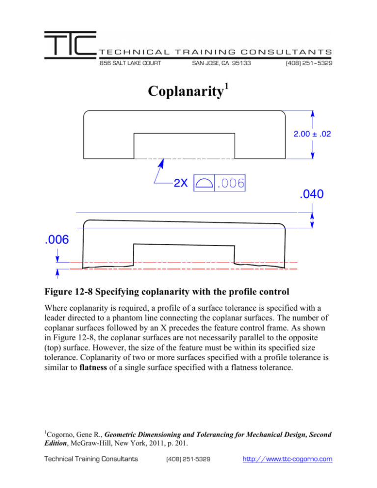
856 SALT LAKE COURT SAN JOSE, CA 95133 (408) 251–5329 Coplanarity1 2.00 ± .02 2X .040 .006 Figure 12-8 Specifying coplanarity with the profile control Where coplanarity is required, a profile of a surface tolerance is specified with a leader directed to a phantom line connecting the coplanar surfaces. The number of coplanar surfaces followed by an X precedes the feature control frame. As shown in Figure 12-8, the coplanar surfaces are not necessarily parallel to the opposite (top) surface. However, the size of the feature must be within its specified size tolerance. Coplanarity of two or more surfaces specified with a profile tolerance is similar to flatness of a single surface specified with a flatness tolerance. 1 Cogorno, Gene R., Geometric Dimensioning and Tolerancing for Mechanical Design, Second Edition, McGraw-Hill, New York, 2011, p. 201. Technical Training Consultants (408) 251-5329 http://www.ttc-cogorno.com Where a parallel surface is specified as a datum feature and the datum feature is referenced in the profile feature control frame, as shown in Figure 12-9, the toleranced surfaces must be coplanar and parallel to the datum feature within the tolerance specified in the feature control frame. If the 2.00-inch dimension is specified with a plus or minus tolerance, as shown in Figure 12-9, the .006 profile tolerance zone must be parallel to datum feature A and fall within the .040 size tolerance zone. That is, the .006 tolerance zone may float up and down within the .040 size tolerance zone but must remain parallel to datum feature A. Coplanarity of two or more surfaces specified with a profile tolerance that includes a datum reference identifying a parallel surface is similar to parallelism of a single surface specified with a parallelism tolerance. A 2.00 ± .02 2X .040 .006 The Profile Tolerance Zone Must be Parallel to Datum Feature A Figure 12-9 Two coplanar surfaces parallel to a datum feature Technical Training Consultants (408) 251-5329 http://www.ttc-cogorno.com A 2.000 2X .006 2.000 The Profile Tolerance Zone Must be Parallel and Located to Datum Feature A Figure 12-10 Two coplanar surfaces parallel and located to a datum feature If the 2.000-inch dimension is basic, as shown in Figure 12-10, the true profile of the two coplanar surfaces is a basic 2.000 inches from datum feature A. The tolerance zone, consisting of two parallel planes .006 apart, is evenly disposed about the true profile. Where the basic dimension is specified, the total tolerance for the size, parallelism, and coplanarity is .006. Coplanarity of two or more surfaces specified with a profile tolerance, a basic dimension, and a datum reference is treated like any other profile control. 1.000 .006 .006 Figure 12-11 Profile of a surface for stepped surfaces A profile tolerance may be used to control two or more stepped surfaces that are required to be flat and parallel within a specific tolerance. The profile tolerance for the part shown in Figure 12-11 controls the two surfaces, flat, parallel, and stepped 1 basic inch form each other, within a tolerance of .006. Technical Training Consultants (408) 251-5329 http://www.ttc-cogorno.com Ø2.000-2.010 C 1.500 B 4.000 2X A Figure 12-12 Two coplanar surfaces specified as a datum feature Coplanar surfaces may be used as a datum feature. If this is the case, it is best to attach the datum feature symbol to the profile feature control frame, as shown in Figure 12-12. This tolerancing arrangement leaves no doubt that datum feature A consists of the two coplanar surfaces. Technical Training Consultants (408) 251-5329 http://www.ttc-cogorno.com


