Reinforced Concrete Design: Bond, Anchorage, Development Length
advertisement
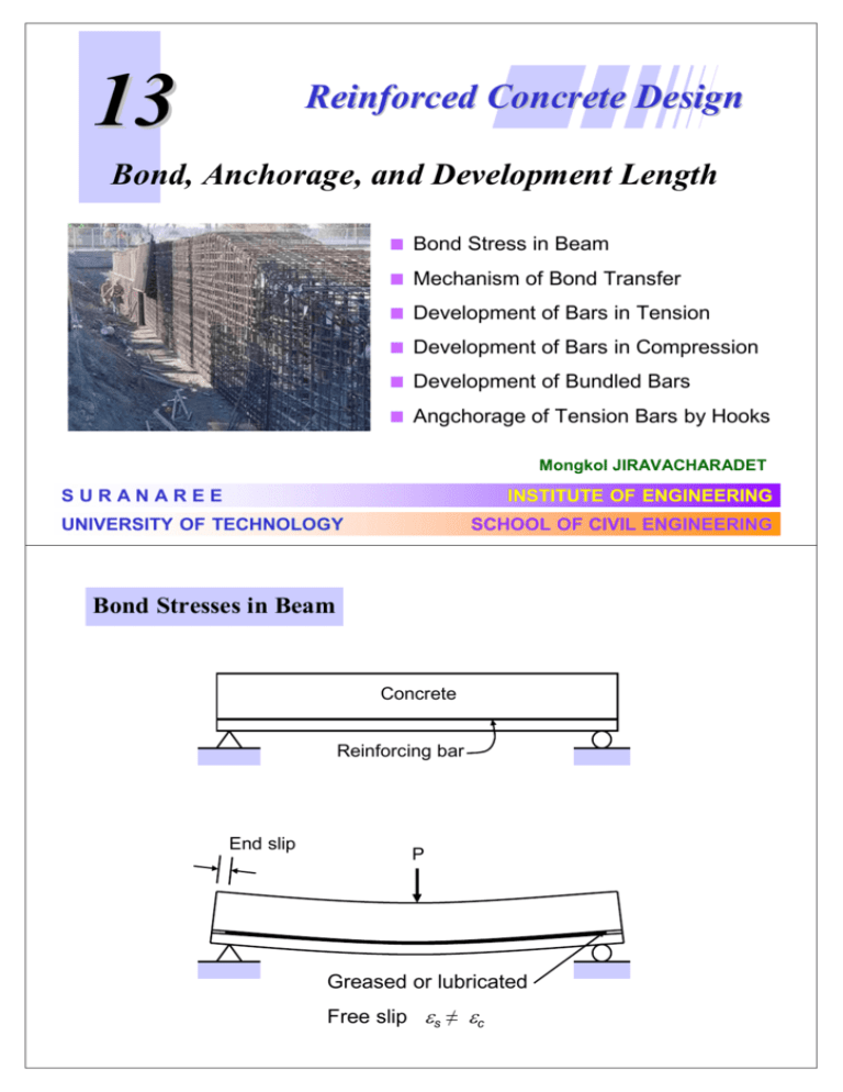
13 Reinforced Concrete Design Bond, Anchorage, and Development Length Bond Stress in Beam Mechanism of Bond Transfer Development of Bars in Tension Development of Bars in Compression Development of Bundled Bars Angchorage of Tension Bars by Hooks Mongkol JIRAVACHARADET SURANAREE INSTITUTE OF ENGINEERING UNIVERSITY OF TECHNOLOGY SCHOOL OF CIVIL ENGINEERING Bond Stresses in Beam Concrete Reinforcing bar End slip P Greased or lubricated Free slip εs ≠ εc Bond forces acting on concrete Bond forces acting on steel Tied-arch action in a beam with little or no bond (Round bar reinforcing) Mmax jd Little or no bond Bond Stress Based on Simple Cracked Analysis [ ΣMO = 0 ] C + dC C j d (dT ) = V (dx ) jd V dT V = dx jd V [ ΣFx = 0 ] T + dT T O dx u Σo dx = dT u 1 T + dT T ก = As f s = = π d Lu 4 fs = ก ก 2 2 u= V Σo j d ก π d2 1 Elastic Cracked Section Equation Critical section L π d Lu = π d2 L = 4 fs d fs 4u (WSD) ก : ก ua = ก ua = ก : 2.29 f c′ db ≤ 25 kg/cm2 3.23 f c′ ≤ 35 kg/cm 2 db ua = 1.72 f c′ ≤ 28 kg/cm 2 * กกก !"!ก 11 กก./&.2 * ก(ก) ก *! ก+ก 30 &. Nominal Bond Strength ก : ก un = ก un = ก : 4.51 f c′ db ≤ 39.4 kg/cm 2 6.39 f c′ ≤ 56.2 kg/cm 2 db un = 3.44 f c′ db ≤ 56.2 kg/cm2 * กกก !"!ก 17.6 กก./&.2 Steel Force and Bond Stress Cracked concrete segment M M T T u stresses on bar steel tension T T= M jd u= 1 dT Σ o dx bond stress u Actual Distribution of Flexural Bond Stress CL T= M jd Actual T u= V Σ o jd Actual u Mechanism of Bond Transfer R u ∆T ∆T Friction & chemical adhesion between concrete and steel R R Reaction of concrete on ribs R R Forces exerted by ribs on concrete Failure modes R R Side-split failure V-notch failure R Vertical cracking of bottom cover Ultimate Bond Strength Cylindrical zones of circumferential tension Reinforcement Radial component of bearing pressure Circumferential tensile stresses Minimum Bar Covering and Spacing Minimum bar covering ( cb ) cb 2cs cs Minimum bar spacing ( 2cs ) Splitting of concrete along reinforcement DEVELOPMENT LENGTH Embedment length to develop full tensile strength of bar ld T=0 a T = Ab fs Requirement: l ≥ ld : development length Factors influencing ld - Tensile strength of concrete fct - Steel covering - Bar spacing - Stirrup ACI 12.2 – Development of deformed bars in tension Development length Ld shall be determined from either 12.2.2 or 12.2.3, but shall not be less than 12 in. 0.28 fy α β γ λ 12.2.3 – For deformed bars Ld shall be: Ld = db fc′ c + K tr db Atr fyt in which the term (c + Ktr)/db shall not be taken greater than 2.5, and K tr = 105 s n c = the smaller of (a) distance from center of bar to the nearest concrete surface (b) half the center-to-center spacing of the bars Atr = total cross-sectional area of all transverse reinforcement within spacing s fyt = yield strength of transverse reinforcement s = maximum spacing of transverse reinforcement within Ld n = number of bars being developed along the plane of splitting. It shall be permitted to use Ktr = 0 as a design simplification even if transverse reinforcement is present. Atr Definition of Atr Potential plane of splitting ACI 12.2.5 – Excess reinforcement Reduction in Ld shall be permitted where reinforcement in a flexural member is in excess of that required by analysis (As required)/(As provided) Ld Reduction for large cover and wide bar spacing: 0.8 Heavily confined reinforcement: 0.75 Modifying Multipliers of Development Length in Tension α Bar location: β Coating factor: (a) Top reinforcement α = 1.3 (b) Bottom bars α = 1.0 (a) Epoxy-coated cover < 3db or clear spacing < 6db β = 1.5 (b) All other epoxy-coated β = 1.2 (c) Uncoated reinforcement β = 1.0 Note: α × β need not be taken > 1.7 γ Bar-size factor: λ Lightweight aggregate factor: (a) DB20 and smaller γ = 0.8 (b) DB25 and larger γ = 1.0 (a) Lightweight aggregate concrete λ = 1.3 (b) Normal weight concrete λ = 1.0 ACI 12.2.2 – Simplified Equation for Development Length For deformed bars Ld shall be as follows: c + K tr = 1.5 db DB20 and smaller (γγ = 0.8) DB25 and larger (γ = 1.0) Case A: (1) covering = db clear c-c = db min. stirrup ld 0.15 f y = αβλ db f c′ ld 0.19 f y = αβλ db f c′ (2) covering = db clear c-c = 2db (A - 1) (A - 2) ld 0.23 f y = αβλ db f c′ ld 0.28 f y = αβλ db ′ fc (B - 1) (B - 2) set Case B: others Development Length of Bars in Compression ldb = 0.075 db f y f c′ ≥ 0.0043 db f y Modification factors: - Excess reinforcement As req’d / As prv’d - Spiral stirrup dia. ≥ 6 mm, pitch ≤ 10 cm 0.75 - Tied stirrup DB12, spacing ≤ 10 cm 0.75 Development Length for Bundled Bars when space for proper clearance is restricted - No more than 4 bars bundled in contact - Bar larger than DB36 shall not be bundled in beams - Termination of each bar must be different at least 40db - Development length based on single bar in the bundle - Increase 20% for 3 bars - Increase 33% for 4 bars Anchorage of Tension Bars by Hooks When straight embedment is not enough a) Standard Bar Hook D = diam of bend db T 180o Hook 4 db ≥ 6 cm D db Min. Dia. of Bend (D) T 90o Hook DB10 - DB25 DB28 - DB36 DB40 - DB60 12 db For stirrup and tie anchorage only: db (a) For DB16 or smaller D T 6db db (b) For DB20 or DB25 D T 12db db (c) For DB25 or smaller T 135o 6db 6db 8db 10db b) Development length and Hook Combined actions: Ldh Ld - Bond along straight length - Anchorage provided by hook T db 12db Critical section full bar tension T db 4db ≥ 6 cm 4db Ldh Basic development length with fy = 4,000 kg/cm2 Lhb = 318d b f c' Ldh = Modification factor × Lhb Modification factors: - Bar with fy other than 4,000 ksc - DB25mm and smaller side cover not less than 4 cm 90o hook cover hook not less than 5 cm fy / 4,000 0.7 - DB25mm and smaller hook enclosed within stirrup along ldh stirrup spacing not greater than 3db 0.8 - Excess reinforcement As reqd / As prvd - Lightweight concrete 1.3 - Epoxy coating 1.2 EXAMPLE 11-1 Anchorage of a Straight Bar A 40-cm-wide cantilever beam frames into the edge of a 40-cm-thick wall, as shown. At ultimate, the DB25 bars at the top of the cantilever are stressed to their yield strength at point A at the face of the wall. Compute the minimum embedment of the bars into the wall. The concrete is normal-weight concrete with a strength of 240 ksc. The yield strength of the flexural reinforcement is 4,000 ksc. DB16 at 30 cm O.C. B Ld Construction joint 45 cm 3DB25 A 39 cm Construction joint 40 cm Wall 1.5 m 1. Find the spacing and confinement case. There are no stirrups or ties in the wall, but there are DB16 at 30 cm o.c. vertical bars outside of the 3DB25 Clear side cover = 4 + 1.6 = 5.6 cm (2.24db) Clear spacing = (40 – 2(4+1.6) – 3x2.5) / 2 = 10.65 cm (4.26db) ก α = 1.3 ก"!01ก& β = 1.0 ก +ก0ก λ = 1.0 Since the clear spacing between the bars is not less than 2db and the clear cover exceeds db, case (A-2) applies. 2. Compute the development length. From (A-2) : Ld = 0.19 fy α β λ fc′ db = 0.19(4,000)(1.3)(1.0)(1.0) × 2.5 = 159.4 cm 240 Use development length Ld = 160 cm Ld = 3. Compute the development length. Detailed equation : 0.28 fy α β γ λ c = the smaller of (a) c + K tr fc′ db db distance from center of bar to the nearest concrete surface: the side cover is 4 + 1.6 + 2.5/2 = 6.85 cm; 40 − 2 × 6.85 half the center-to-center spacing of the bars, or 0.5 = 6.58 cm 2 Therefore, c = 6.58 cm. K tr = A tr fyt 105 sn = 4.02 × 4,000 = 1.7 cm 105 × 30 × 3 s = spacing of the transverse reinforcement within Ld = 30 cm Atr = transverse steel area crossing splitting plane within spacing s = DB16 at 30 cm each face = 2 x 2.01 = 4.02 cm2 fyt = 4,000 kg/cm2 for the wall steel n = number of bars being anchored = 3 6.58 + 1.7 c + K tr = = 3.31 > 2.5 2.5 db 0.28 fy α β γ λ c + K tr fc′ db = 122.2 cm db = 0.28 × 4,000 × 1.3 × 1.0 × 1.3 × 1.0 × 2.5 240 × 2.5 Use development length Ld = 125 cm Construction joint A 3DB25 B Ld = 125 cm Construction joint Wall 1.5 m 45 cm Ld = USE 2.5 39 cm (b) Bar Cutoff and Bend Points in Beams Moment capacity of beam: 2 bars a M = As f y d − 2 4 bars C L 5 bars Ld Ld Ld 5M Required moment Mu / φ Moment capacity Mn Face of support Bar Cutoff requirements of the ACI Code Moment capacity Inflection point for +As Inflection point for -As -M of bars M Ld Bars M +M Moment capacity of bars O Greatest of d , 12db or Ln/16 CL of span for at least 1/3 of -As d or 12db Ld Bars L Bars N 15 cm for at least 1/4 of +As Ld d or 12db Ld Bars O Development of Reinforcement at Simple Supports La At point A, Mu = φMn of bars continuing into the support Mn /Vu ACI: Distance from A to bar end ≥ Ld ≥ Ld Approximate A Mu Vavg (say, 0.9Vu )x = φ M n φMn → x= Mn Vu La = Straight length beyond c.g. support Vu ACI: Embedment length Vavg La + 1.3 x Mn ≥ Ld Vu 1.3 for less tendency to split due to confinement at support Development of Reinforcement at Inflection Points Locate away from support → no confinement → 1.3 factor not apply Actual La Usable La ACI: Embedment length Mn /Vu Mu A φMn Inflection point Vu Usable La + Mn ≥ Ld Vu Usable La = Actual La but not exceed the larger of 12db or d Standard Cutoff and Bend Points for Bars For approximately equal spans with uniformly distributed loads L1/4 L1/3 L2/3 L2/3 0 cm 15 cm 15 cm L2/8 L1/8 L1 L2 L1/3 L1/7 L2/3 L1/4 L2/4 L2/4 6.3 4546ก7ก! ! !ก8999 +ก!07)+9 wu = 8.0 ก9 f’c = 280 กก./&.2, fy = 4,000 กก./&.2, b = 40 &., h = 60 &. 7ก 8 4 &. Exterior column Interior column wu Ln = 7.6 m 1. กก!"##$ a. ก7?076!@ ?7A Interior face of exterior support -Mu = wuLn2/16 = 8(7.6)2/16 = -28.88 t-m Mid span positive +Mu = wuLn2/14 = 8(7.6)2/14 = 33.01 t-m Exterior face of first interior support -Mu = wuLn2/10 = 8(7.6)2/10 = -46.21 t-m Exterior face of first interior support Vu = 1.15wuLn/2 = 1.15(8)(7.6)/2 = 34.96 t-m b. 546ก@ ?99 @9ก 8 4 &. ก0ก DB10 7ก @ ?99 DB25 DB28 ! d ≈ 60-4-1.0-1.4 ≈ 53.6 &. Mu As required Bars As provided - 28.88 t-m 15.97 cm2 4DB25 19.63 cm2 + 33.01 t-m 18.44 cm2 4DB25 19.63 cm2 - 46.21 t-m 26.76 cm2 2DB25+3DB28 28.29 cm2 A 4DB25 B 2DB25+3DB28 4DB25 B A 40 cm 40 cm 4DB25 DB10@0.20m 60 cm 2DB25 3DB28 60 cm DB10@0.20m 4DB25 Section A-A 4DB25 Section B-B

