2.2. Inductor volt-second balance, capacitor charge balance, and the
advertisement
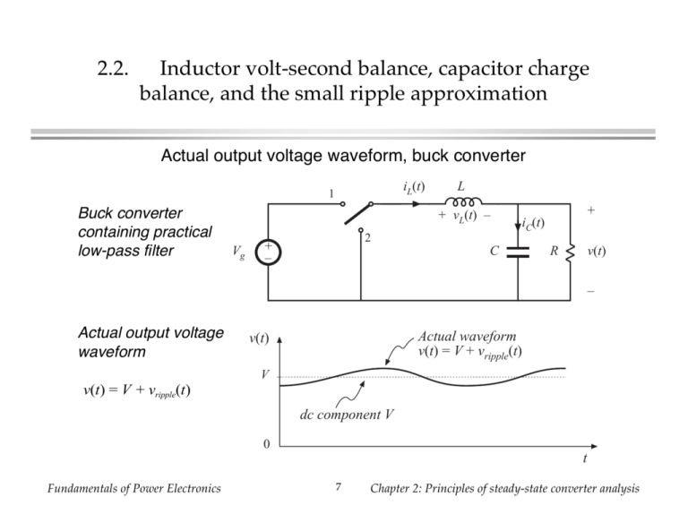
2.2. Inductor volt-second balance, capacitor charge balance, and the small ripple approximation Actual output voltage waveform, buck converter iL(t) 1 Buck converter containing practical low-pass filter L + vL(t) – Vg + iC(t) 2 + – C R v(t) – Actual output voltage waveform Actual waveform v(t) = V + vripple(t) v(t) V v(t) = V + vripple(t) dc component V 0 t Fundamentals of Power Electronics 7 Chapter 2: Principles of steady-state converter analysis The small ripple approximation Actual waveform v(t) = V + vripple(t) v(t) v(t) = V + vripple(t) V dc component V 0 t In a well-designed converter, the output voltage ripple is small. Hence, the waveforms can be easily determined by ignoring the ripple: vripple < V v(t) ≈ V Fundamentals of Power Electronics 8 Chapter 2: Principles of steady-state converter analysis Buck converter analysis: inductor current waveform iL(t) 1 L + vL(t) – original converter 2 + – Vg + iC(t) C R v(t) – switch in position 1 iL(t) L L + vL(t) – Vg + – switch in position 2 + iC(t) C R Vg v(t) + – iL(t) iC(t) C R v(t) – – Fundamentals of Power Electronics + + vL(t) – 9 Chapter 2: Principles of steady-state converter analysis Inductor voltage and current Subinterval 1: switch in position 1 iL(t) Inductor voltage L + vL(t) – iC(t) vL = Vg – v(t) Vg Small ripple approximation: + – + C R v(t) – vL ≈ Vg – V Knowing the inductor voltage, we can now find the inductor current via vL(t) = L diL(t) dt Solve for the slope: diL(t) vL(t) Vg – V = ≈ L L dt Fundamentals of Power Electronics ⇒ The inductor current changes with an essentially constant slope 10 Chapter 2: Principles of steady-state converter analysis Inductor voltage and current Subinterval 2: switch in position 2 L Inductor voltage + + vL(t) – vL(t) = – v(t) Small ripple approximation: Vg + – iL(t) iC(t) C R v(t) – vL(t) ≈ – V Knowing the inductor voltage, we can again find the inductor current via vL(t) = L diL(t) dt Solve for the slope: diL(t) ≈– V L dt Fundamentals of Power Electronics ⇒ The inductor current changes with an essentially constant slope 11 Chapter 2: Principles of steady-state converter analysis Inductor voltage and current waveforms vL(t) Vg – V DTs D'Ts t –V Switch position: iL(t) 1 2 1 iL(DTs) I iL(0) 0 Fundamentals of Power Electronics vL(t) = L diL(t) dt ∆iL Vg – V L –V L DTs 12 Ts t Chapter 2: Principles of steady-state converter analysis Determination of inductor current ripple magnitude iL(t) iL(DTs) I iL(0) ∆iL Vg – V L 0 –V L DTs Ts t (change in iL) = (slope)(length of subinterval) Vg – V DTs 2∆iL = L ⇒ Vg – V L= DTs 2∆iL Vg – V ∆iL = DTs 2L Fundamentals of Power Electronics 13 Chapter 2: Principles of steady-state converter analysis Inductor current waveform during turn-on transient iL(t) Vg – v(t) L – v(t) L iL(Ts) iL(0) = 0 0 DTs Ts iL(nTs) 2Ts nTs iL((n + 1)Ts) (n + 1)Ts t When the converter operates in equilibrium: i L((n + 1)Ts) = i L(nTs) Fundamentals of Power Electronics 14 Chapter 2: Principles of steady-state converter analysis The principle of inductor volt-second balance: Derivation Inductor defining relation: di (t) vL(t) = L L dt Integrate over one complete switching period: iL(Ts) – iL(0) = 1 L Ts vL(t) dt 0 In periodic steady state, the net change in inductor current is zero: Ts 0= vL(t) dt 0 Hence, the total area (or volt-seconds) under the inductor voltage waveform is zero whenever the converter operates in steady state. An equivalent form: T s 1 0= v (t) dt = vL Ts 0 L The average inductor voltage is zero in steady state. Fundamentals of Power Electronics 15 Chapter 2: Principles of steady-state converter analysis Inductor volt-second balance: Buck converter example vL(t) Vg – V Inductor voltage waveform, previously derived: Total area λ t DTs –V Integral of voltage waveform is area of rectangles: Ts λ= vL(t) dt = (Vg – V)(DTs) + ( – V)(D'Ts) 0 Average voltage is vL = λ = D(Vg – V) + D'( – V) Ts Equate to zero and solve for V: 0 = DVg – (D + D')V = DVg – V Fundamentals of Power Electronics 16 ⇒ V = DVg Chapter 2: Principles of steady-state converter analysis The principle of capacitor charge balance: Derivation Capacitor defining relation: dv (t) iC(t) = C C dt Integrate over one complete switching period: vC(Ts) – vC(0) = 1 C Ts iC(t) dt 0 In periodic steady state, the net change in capacitor voltage is zero: 0= 1 Ts Ts iC(t) dt = iC 0 Hence, the total area (or charge) under the capacitor current waveform is zero whenever the converter operates in steady state. The average capacitor current is then zero. Fundamentals of Power Electronics 17 Chapter 2: Principles of steady-state converter analysis
