Operator Manual for WDP4 / WDG4 prepared by Hubli Shed
advertisement
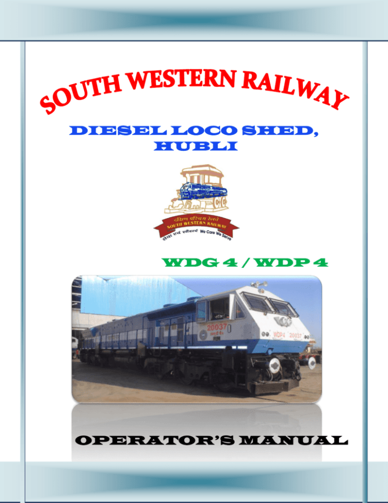
DIESEL LOCO SHED, HUBLI WDG 4 / WDP 4 OPERATOR’S MANUAL WDP4 / WDG4 Locomotive Cranking Procedure o Put on the hand brake o Check all lubricant and coolant levels o Make sure that LLOB, Low water button and Low crank case vacuum button are pressed in. o Make sure that OSTA is in reset position (Top of handle should be tilted towards left of locomotive, away from the start/ prime switch side) o Make sure that the Isolate / Run switch is in Isolate position o Ensure that 0n the control stand – o Engine Run switch is down (0ff) o Control /FP breaker is up (ON) o Generator field switch is down (OFF) o MU RUN button is pressed in o Ensure that on the working control stand – o Reverser handle is applied and is centered o Throttle is in ‘Lead in’ o Auto brake is applied to full application position. o Lead / Trail switch is in ‘Lead in’ o Ensure that on the non –working control stand – o Reverser handle is removed o Throttle is in Idle o Auto brake is in Full service position o Independent brake is released o Lead / trail switch is in Trail position o Ensure that start Fuse is in position and put ON the battery knife switch. o On the breaker panel, put on necessary white labeled breakers (please note that all breakers have to be put for ON position). The Air dryer breaker must be put on. o Put on all BLACK labeled breakers. o Put on the Turbo lube pump breaker (Left side breakers of the two breakers with yellow and black striped labels) o Put on the computer breaker (Right side breakers of the two breaker with yellow and black striped labels) o Go to the Engine PRIME / CRANK switch and hold the engine switch to PRIME side (left side). If the shutdown procedure was followed properly earlier, the fuel pump motor will start (the motor o o o o sound can be heard ). If the fuel pump motor does not start, wait for 15-20 minutes and try again. Keep holding the Engine PRIME/ CRANK to prime side and see that the fuel secondary sight glass is full of fuel and shows no bubbles. Out of the two sight glasses, the one closest to engine block should be full and one away from the engine block should be empty. Hold the Engine PRIME/ CRANK switch to CRANK side and press the lay shaft a little to crank the engine. Release the lay shaft and the switch when you feel the lay shaft being pulled from your hand .(only for WDG4 Locomotive) Caution: Excessive pressing of the lay shaft will over speed the engine and OST will trip causing the engine to shut down. In the cab, if you see a No Aux Gen Out put message, switch the computer breaker off, wait 20-25 second and switch on again. WDP4 / WDG4 LOCOMOTIVE SHUT DOWN PROCEDURE o Put on the hand brake o Turn Isolate / Run switch to isolate position. o On the control stand, put Engine Run Switch down (OFF) Control? FP breaker up (ON) Generator field switch down (OFF) o On the working control stand Put Throttle in idle Center and remove reverser handle Release Auto brake Apply Independent brake to full application position. Ensure Lead / Trail switch is in ‘Lead in’ o On the non-working control stand Ensure that reverser handle is centered and removed. Ensure that Throttle is in idle Ensure that Auto brake is in full service position. Ensure that independent brake is released Ensure that Lead / Trail switch is in Trail Position. o Press EFCO (Red) button on the Control panel fill the engine stops o On the breaker panel. Put all Black labeled breakers down (OFF) Put on all while labeled breakers down (OFF) o Make sure that the Turbo lube pump motor is running (Sound of the motor can be head by standing on the foot board near lube oil dipstick location) o Wait for 35 minutes (till the turbo pump lube pump motor stops running) o Switch off computer breaker o Switch off TLPR breaker o Open battery knife switch PROCEDURE FOR CHANG OF CONTROL STAND Note : Please follow the steps given below in the exact sequence to ensure error free changing of control stand o o o o o o o o o o o On the control stand to be made non- working – Put Throttle in idle. Center and remove reverser handle Apply Auto break full service position Release independent brake Wait till the brake cylinder pressure needle (Red) stabilizes Press down and rotate the Lead / Trail switch to Trail position. On the non –working control stand to be made working – Apply the reverser handle and ensure that it is centered Ensure that Throttle is in Idle Release Auto brake o Apply Independent brake o Press down and rotate the lead /Trail switch to Lead in position. WDG4 LOCOMOTIVE AIR BRAKE SELF TEST Note: Do not do self test unless you have a serious problem in the air brake system. Wrong setting of air brake equipment before conducting a self test can lead to a failed test self and PCS becoming ON. o Apply handbrake on locomotive and take all precaution as per laid down procedures to secure the train and locomotive against rolling. o Close the BP & FP angle cocks, MR Equalizing and BC Equalizing cut out cocks at both ends of the locomotive o On the working control stando Ensure that the Lead / Trail switch is in Lead position. o Center reverser handle o Put Throttle in Idle. o Release Auto brake and Independent brake o Wait till the brake cylinder pressure needle (Red) drops to zero (If PCS is open, the needle will not drop. This is alright .proceed to next step) o On the non –working stand – o Ensure that the Lead /Trail switch is Trail position o Ensure that the reverser handle is centered and removed o Throttle is in Idle o Put the Auto brake handle in Full service position and Independent brake handle in full application position. o From the EM- 2000Display Main Menu, select SELF TESTS o Press F2 key to select NEXT (next page) o Select AIR BRAKE SELF TEST o Press F1 key to select CONTINUE o The air brake test will start now. Wait till the Air Brake test passed message appears. o Press F4key to EXIT the test. o Open the BP& FP angle COCs, the MR Equaling COCs and the BC Equaling COCs which have been closed to set up the locomotive for required mode of operation (lead, trail, single head, banking etc.) Note: If PCS does not reset in some cases by performing the test on one control stand, change control stand as per proper procedure and perform the test again with the other control stand as the working control stand. AIR BRAKE EQUIPMENT SET UP Note: for BP& FP angle COCs, position parallel to pipe indicates OPEN COC and position perpendicular to pipe indicates CLOSED COC. BP & FP angle COCs Closed Position Open Position ________________________________________________ - Other Pipe COCs Closed Position Open Postion Setting up a locomotive as a single head unit of MU lead unit. o Ensure that your locomotive and train are coupled and secured properly. o Ensure that your locomotive is cranked and the computer breaker and Micro Air Brake breaker are ON (up). o If you are setting up the locomotive as a lead unit in MU, please set up all other trailing locomotives as Trail units first as per procedure given under, ‘setting a locomotive up as MU Trail unit, and the proceed with the set up as indicated below. o Close BP & FP cut cocks on the free end of the locomotive. Close MR equalizing and BC equalizing cut out cocks located under the foot board on the under frame pipes on the free ends of the locomotive. o Ensure that the truck COCs are open on both the trucks. o Couple BP pipe to the load (BP pipe is the lower pipe among the two big pipes with angle COCs near the coupler) and open BP COC. If working on a twin pipe system (with BP and FP both), couple FP pipe to the load and open FP COC. o Open BP cut out cock (and FP COC if working on twin pipe system) on the load end of the locomotive. Close MR equalizing and BC equalizing cut out cocks on the load end of the locomotive These cocks are located under the foot board on the pipes running on the under frame of the locomotive. o Ensure that palm ends of all unused pipes are secured on dummy palm ends provided for this purpose. o On the non-working control stand, check that Reverser is centered and removed Throttle is idle Independent brake is released and Auto brake is in full service position. Lead / trail switch is in Trail. On the working control stand, check that Reverser is centered and handle is available. Throttle is idle. Independent brake is applied and Auto brake is released (caution: Take all precautions as per extent rules to prevent rolling of you train before doing this). Lead / Trail switch is in Lead (Always remember to press the switch down before you rotate the switch to any position. o Ensure that – MR is between 8-10 Kg/Cm2 BP is 5 Kg/Cm2 BC is 4.35 Kg/Cm2 (when the independent brake is fully applied) PCS light is OFF o Test your auto and independent brakes. See physically whether brake cylinder pistons on the locomotive and the load apply and release properly. o Do not forget to remove the hand brake on the locomotive and the hand brakes or nay other means of securing the load (if applied) after your train and locomotive brake are fully active and you are ready to move the train. Setting up a Locomotive as a MU Trail unit o Ensure that the locomotive is coupled properly to other locomotive/train and secured properly o Ensure that the locomotive is cranked and the computer breaker and Micro Air Brake breaker are ON(up) o On the end of the locomotive which is connected to another locomotive o Couple BP & FP pipes to the other locomotive (BP pipe is the lower pipe among the two big pipes with angle COCs near the coupler) and open BP & FP angle COCs. o Open BP & FP cut out cocks on the locomotive end connected to the other locomotive. Open MR Equalizing & BC Equalizing cut out cocks on the end of the locomotive connected to the other locomotive. These cocks are located under the foot board on the pipes running on the under frame of the locomotive. o On the end of the locomotive which is connected to load: o Couple BP pipe to the load (BP pipe is the lower pipe among the two big pipes with angle COCs near the coupler) and open BP angle COCs. If working on a twin pipe system (with BP & FP both), couple FP pipe to the load and open FP angle COC. o Open BP cut out cocks ( and FP OC if working on a twin pipe system) on the load end of the locomotive. Close MR Equalizing and BC equalizing cut out cocks on the load end of the locomotive. These cocks are located under the foot board on the pipes running on the under frame of the locomotive o Ensure that the truck COCs are open on both the trucks o Ensure that the truck COCs are open on the both the trucks o Ensure that palm ends of all unused pipes are secured on the dummy palm ends provided for this purpose. o On the both control stand, ensure Reverser centered and removed Throttle in idle Independent brake to full and Auto brake is in Full service position After brake pipe exhaust stops, put the lead / Trail switch is in Trail.. (Always remember to press the switch down before you rotate the switch to any position) o Ensure that – o MR is between 8-10 Kg/cm2 o BP is 5 Kg/cm2 (when the auto brakes on lead locomotive are released) o PCS light is OFF o Test that the brake cylinder operate in conjunction with the lead locomotive when you test it. o Do not forget to remove the hand brake on all trailing locomotives after your train and locomotives brakes are full active and you are ready to move the train. o o o o Setting up a Locomotive for banking o Procedure and setting as a lead locomotive except the following settingso Put Lead/Trail switch in ‘Lead Out’ position on working control stands. Setting up a Locomotive to move dead on formation o Ensure that the locomotive is coupled properly to other locomotives/train and secured properly. o If a locomotive to be moved dead is attached as MU trail to another WDG4/WDP4 locomotive, connect to all MU pipes as per pipe connections given under the procedure give under ‘Setting up a locomotive as a MU Trail unit’. Do not crank the locomotive but set all the control stand handless and switches as mentioned under the same procedure. o If a locomotive is to be moved dead as part of the formation ( not attached behind another WDG4/WDP4 locomotives as MU)o Open the dead engine cut out cock located in the lower corner of the air brake panel (in the Cab) (by putting the handle in ‘Vertical’ position). o Open MR Eq. CC and BC Eq. COC at both ends of the locomotive. o Close BP & FP cut out cocks on the free end of the locomotive o Ensure that the truck COCs are open on the trucks. o Couple BP pipe to the load (BP pipe is the lower pipe among the two big pipes with angle COCs near the coupler) and open BP COC. If working on the twin pipe system (with BP and FP both), couple FP pipe to the load and open FP COC. o Open BP cut out cock (and FP COC if working on twin pipe system) on the load end of the locomotive. These cocks are located under the foot board on the pipes running on the under frame of the locomotive. Note: A slight air blow will be felt at all times of the BC Eq. pipe during such dead operation. This normal and does not affect the development of BC pressure. o Test that the brake cylinders operate in conjunction with the load when auto brakes are applied from the lead locomotive of the train. WDP4 / WDG4 LOCOMOTIVE DO’s AND DONT’s DO’s o DO- Let the locomotive warm up properly to the desired temperature of 125ºF (55ºC) before attempting to move the locomotive. (The locomotive raises engine speed to 3rd notch RPM automatically till the temperature is obtained). o DO- Ensure cranking of the locomotive at least once in 24 hours. Ensure hand barring of the hydraulic lock up if the locomotive to make sure that there is no hydraulic lock up if the engine has not been cranked for more that 24 hours. o DO- Ensure pre-lubrication of the engine (to be done by maintenance staff) if the engine has not been cranked for more that 48 hours. o DO- Follow correct cranking and shut down procedures to enhance engine and turbo life. o DO- Ensure all brakes are released properly before moving the locomotive. DONT’s o DO NOT – Raise the engine beyond 4th notch without load. o DO NOT – Spill tea / coffee or other eatables on control stand or cab (The sensitive air brake equipment in control stand and air brake compartment will be damaged) o DO NOT – Permit incorrect lube oil, governor oil or coolant water to be added in the locomotive. o DO NOT - Permit bad quality sand or wet sand to be added in the sand boxes. o DO NOT – Stable the locomotive without putting on the hand brake. o DO NOT – Move your train unless you physically check that the brakes are active. LUBRICANTS AND COOLANT WATER ADDITIVE PERMITTED ON WDG4 LOCOMOTIVE Engine crank case lube oil o RR520 MR from M/s.IOC or MR RR 517M from M/s.BPC. Please check the sticker indicating the brand name stuck on crank and on lube oil strainer. Compressor Sump oil o Servo Press 100 from M/s.IOC Governor Oil o Same as main engine oil Coolant o Pink coloured coolant with NALCO 2100 additive Gear Case Oil Mobile SHC634 from Mobile MAJOR COMPONENTS LOCATION TURBO LUBE PUMP FUEL PUMP RA DIA TO R Pressure relief Handle RADIATOR FANS EXPANSION TANK OIL LUBE ER COOL COOLING COILS BATTERY KNIFE SWITCH Fuel Sight Glass By pass Return Fuel secondary filters OSTA COMPANION ALTERNATOR ALTERNATOR GOVERNOR FUEL PRIMARY FILTER F I E L D WATER PUMPS LUBE OIL FILTER DRUM FLYWHEEL LAY SHAFT AUXILIARY MOTORS INTER COOLER HOD OIL SEPARATOR EPD M R P T COMPRESSOR FCS FCF LWS ENGINE START FUEL PRIME ECC II EDUCTOR TUBE CRANK CASE ENGINE START SWITCH CS I C L E A N START MOTORS A I R C O M P A R T M E N T T C C II T C C I E M 2 0 0 0 BLOWER MOTOR C C B TURBO GRIDS CS II BLOWER MOTOR CLEAN AIR COMPARTMENT AUXILIARY GENERATOR Aux.Gen.DRIVE SHAFT CCB CYCLONIC FILTERS A C/S DB TM BLOWER EPA B C/S I II III BP BC BCEQ DUST EXHAUST MOTOR AFTER COOLER TURBO FAULT CODE SCREEN BAGGY TYPE AIR FILTERS BCT TO AIR GALLERY BPT ELECTRONIC BLOWER MOTOR DEAD ENGINE COC EPD- ENGINE PROTECTION DEVICE LWS- LOW WATER SWITCH CRANK CASE- LOW VACUUM CRANK CASE TRIP BUTTON TCC- TRACTION CONTROL CABINET CCB- COMPUTER CONTROLLED BRAKE SYSTEM HOD- HOT OIL DETECTOR MRPT-MAIN RESERVOIR PRESSURE TRANSDUCER AIR BRAKE ELECTRICAL JUMPER CONNECTOR CONTROL STAND CHANGING PROCEDURE I. CONDITIONS BEFORE CHANGING CONTROL STAND 1. locomotive is to be stopped (Zero speed) 2. Isolation switch to be kept in ‘isolate’ position. II. WORKING CONTROL STAND CHANGING TO NON/WORKING CONTROL STAND. 1. Remove reverser handle. 2. Keep Auto Brake to full service position, Wait till EQ/BP, pressure stabilizes at about 4.0 KgKm2. 3. Release independent brake handle and BC pressure drops to 4.0 Kg/cm2 Note: DO NOT BAIL OFF 4. Press down Lead/Trail switch and bring to trail position. Equalising Reservoir pressure drops to zero. III. NON-WORKING CONTROL STAND CHANGING TO WORKING CONTROL STAND 1. Pressure down/Lead Trail switch and keep in lead position. ER pressure builds up to 4.0 Kg/cm2. 2. Keep independent Brake handle to full application position. BC pressure build upto 5.0 Kg/cm2. 3. Keep Auto Brake handle to RUN position. BP Builds up to 5.0KG/cm2. 4. Further loco can be operated from changed control stand providing Reverser handle and keeping isolation switch in RUN position. MU OPERATION Making MU CONSIST The following procedure should be carried out when coupling locomotive for MU operation. 1. First check both locos respectively i.e., ground inspection, engine room inspection secure control stands. 2. Couple both the units and stretch them to ensure couplers are locked. 3. Connect 27 conductor control electrical jumper cable between both the locos. 4. Set cab controls for trailing unit operation as mentioned previously i.e. setting lead/trail setup switch to train position. Remove directional handles (reversers). 5. From both controllers to connect all air brake hoses such as MREP, BP,BCEP & FP between both the locos. 6. Open air hose cut-out cocks between both the locos and cut-out cocks to be closed on the other ends. 7. Using the lead locomotive, apply automatic brakes and check brakes are applied on both loco. Then release automatic brakes and ensure brakes are released on both the locos. 8. Apply independent brake and ensure brakes are applied and using quick release, ensure brakes are released on the locos. 9. Ensure tractive effort meter response through the throttle notch on both locos in both directions. 10. Check dynamic brake working on both locomotives. COUPLING THE LOCOMOTIVE TO TRAIN Move the loco motive gently, couple locomotives to the formation and make the following checks. 1. Ensure couplings are locked properly by stretching. 2. Connect all brake hoses to formation and open cut-out-cocks. 3. Observe MR pressure build-up ( if pressure falls to LOW level, engine speed will increase to 2nd notch automatically and EM 2000 will display ENGINE SPEED INCREASE –LOW AIR PRESSURE provided isolation switch is in run position). 4. MR pressure to be built-up to required pressure. SECTION 2. FUEL SYSTEM INTRODUCTION A pictorial diagram of the fuel oil system is shown below. Fuel is drawn from the storage tank through a fuel suction strainer by a motor driven positive displacement gear type pump. Some of the fuel is pumped through a preheater, and some is directed through an Amot Mixing Valve. Warm fuel from the preheater goes to the Amot Valve where it is mixed with fuel from the pump. Fuel, which exits the Mixing Valve, first flows through a strainer and then through the Primary Fuel Filter , and the Engine Mounted Filters. 1&2. Primary Fuel Filter. 3. By Pass Valve 4.Fuel Pump Motor 5. Fuel Preheater 6. Thermostatic Mixing Valve. 7. Suction Strainer 9/Diesel Engine 10. Fuel Injector. Figure 2-1 Fuel Oil System After passing through the engine mounted dual-element filter, the fuel flows through manifolds that extend along both banks of the engine, these manifolds supply fuel to the injectors. The fuel pump delivers more fuel oil to the injectors than is injected into the cylinders. The excess fuel is used to cool and lubricate the close tolerance injector parts. Fuel returning from the injectors passes through the “return fuel” sight glass and back to the fuel tank. Refer to Figure 2-1. A relief valve at the inlet to the “return fuel” sight glass establishes a fuel back pressure, thus maintaining a positive supply of fuel for the injectors. Section -3 LUBRICATING OIL SYSTEM Diagram Lubricating Oil System consists of scavenging pump, main lube oil pump, Lube Oil strainer housing, filter assembly, Lube oil cooler assembly, Turbo Oil filter. Oil from the engine sump is drawn by gear drive scavenging pump though coarse mesh lube oil strainer element and is filtered in lube oil filter tank where 5 filter elements are fitted. From the filter tank oil with pressure is at PSI supplied to main lube oil pump through lube oil cooler and fine mesh lube oil strainer elements. Pressurized lube oil supplied by scavenging pump is further pressurized by a main lube oil pump on a single drive shaft having two pumps one for piston cooling and the other for all bearings. Piston cooling pump supplies pressurized oil to all the pistons through cooling pump supplies pressurized oil to all the pistons through cooling headers on both banks and through piston coolings pipes. This cools the piston crown from bottom and lubricates cylinder liners piston rings while flowing down to the sump. Pressurized oil from main lube oil pump lubricate all 10 main bearings, 8 connecting rod bearings, both end engine gear trains, stub shafts, all cam bushes through drilled oil passage in cam shafts, valve lever mechanism bridge assembly, exhaust valves. Oil for the Turbo is taken from cam gear end lube oil main header through a paper type spin on filter. Oil pipe line from the cam gear end lube oil main header is taken to engine Governor to shut down the engine in order to protect the engine under low oil pressure. One pipe line from the cam gear end lube oil main header is taken to engine Governor to shut down the engine in order to protect the engine under low oil pressure. One 55V AC Electrical Motor (3/4 HP) driver pump circulates engine lube oil to turbo before cranking the engine and after shutting down the engine to protect the turbo running without oil and to cool turbo after the engine is shut down. Timing of switch on and off to be decided. Usually 15 minutes of loco was working below 4th notch and 35 minutes above 4th notch. NOTE: 1. If the filter tank by pass gauge needle shows yellow and red zone, the lube oil filters need change. 2. If the engine is shut down for more than 48 hours the complete lube oil system pre lubrication to be done with an external pump. 3. Do not put off Turbo and Computer Control Circuit breakers immediately after shutting down. A minimum time of 15Min. to be given for cooling down turbo. Capacity of OIL PAN : 950 Liters SECTION 4. COOLING SYSTEM INTRODUCTION The engine-mounted water pumps, draw cooling water from the expansion tank and lube cooler assembly, and pump it into the engine. The heated water leaves the engine, and flows through two radiator assemblies where it is cooled. The cooled water then returns by way of the oil cooler to repeat the closed-loop cycle. Part of the water from the water pumps is piped to the air compressor. There are no valves in this line, air compressor cooling is provided whenever the engine is running. Figure 4-1 Cooling System Diagram Two electronic temperature sensing probes (ETPI-2) are located in the water line from the oil cooler to the inlet of the water pump on the engine left side, near the water temperature gauge. Temperature probe readings are converted by ADA Module (analog to digital to analog) to digital signals used by the EM2000 to control all cooling functions. If the EM2000 computer detects that either temperature probes has failed, it sends a crew message ENGINE TEMOERATURE FEEDBACK FAILURE to the EM2000 display screen and also stores the message in Active memory. If it detects that both probes have failed, it ignores both probe signals, fans remain in last operations status, engine speed goes back to idle and the following message is stored in archive memory, NOT LOADINGENGINE TEMP FB FAILURE. FORCED AIR SYSTEM: The Compartment used for drawing the ambient air through initial air filter (Cyclonic filters) is called the Central Air Compartment. The air that is drawn is used for a. b. c. d. e. Combustion air for diesel engine. Cooling air for main Generator and Companion alternator. Cooling air for Traction Motors. Cooling air for Traction inverter equipment Pressurization of electrical cabinets. The Compartment is located behind the TCC and in front of the engine compartment. This compartment is made up of the partition at rear of TCC#2, the opposite side is made up of the partition fitted around the main generator which consists of two openings one between the engine air filters and Turbo charger and the other for auxiliary generator shaft. The car body hood side, Roof and generator pit complete the air compartment. Two initial air filter panels on either side of the locomotive which are made up of a series of tubes designed to produce cyclonic action, the demands of devices that air from the central compartment creates a suction with in the compartment which draws outside air rapidly through the tubes, dirt and dust particles present in the air which is heavier than air is thrown to the outer wall of the tube and is carried down and sent out through the filter blower motor to the bottom of the locomotive, and then clean air is used for the five above uses in the locomotive. Supplementary use is also made of Traction motor cooling air for 1. To provide pressure to counter act the depression in the central air compartment and unable an aspirator to drain the water from generator pit. 2. To provide filtered air under pressure to the electrical cabinets. Figure 5.1 Central Air System Areas where drivers frequently make mistakes o Checking of compressor oil level: dipstick is to be properly fixed and screwed then opened to check the proper level. o Changing the control stand: proper procedure to be followed. a. Go to working control stand Working control stand present position Change to A9 ( auto brake ) lever in RUN A9(AUTO brake)-----FULL SERVICE BP =5 Kg/cm 2 BP drops to 4.0 Kg/cm2 SA9(DIR BRAKE) LEVER IN FULL BC=5 Kg/cm2 L/T switch in LEAD EQ=5Kg/cm2 SA9(DIR BRAKE) TO RELEASE (R) BC drops to 4.0 Kg/cm2 L/T switch in Trail (TRL) EQ drops to 0 Kg/cm2 b. Go to non working control stand Non working control stand present Change to position L/T switch in (trail) TRL L/T switch LEAD EQ builds to 4 Kg/cm2 SA9 (DIR brake) REL SA9 RUN BC builds to 5 kg/cm2 A9(auto brake )FS A9 RUN BP builds to 5 kg/cm2 o o o o o o o o o o o o o o o Re cycling the circuit breakers: Proper sequence is to be followed. Put isolation switch in isolate position. Reverser to be kept in center position. Put off computer control breaker. Put off concerned breaker (i.e. TCC1,TCC2,AIR BRAKE, AUX,GENERATOR FIELD) Wait for 20 seconds. Put on the concerned breaker Put on computer control breaker. Proper procedure for attaching loco to formation is to be followed. Connect BP and FP ( in case of passenger train ) hosepipes to formation. Place lead trail switch of working control stand to test mode. Open FP & BP Pangle cut out cock of locomotive as well as formation. Place lead trail switch from test mode to lead mode. Procedure for making leading loco as trailing loco and trailing loco as leading loco in MLI Unit. Place leading loco working control stand lead/trial switch in trial mode. o Place lead/trial switch of one of the control stand of trailing loco (Control stand of the desired side, SH of LH) in lead position. o For changing the position of lead trail switch, first press the knob downwards and then turn the switch. o Proper position of GF switch to be ensured before moving the loco. o Driver should not switch off turbo lube pump breaker. o Never switch off AIR DRYER breaker. o Auto drain valve to be kept in auto position after manual draining. o Driver should carefully observe the engine oil level. It should not increase on run. If any increase in the oil level is noted, he should inform to shed. o Similarly the water level should not decrease or fluctuate on cranking or during running the loco. o Never press too much the indication panel switches. o To recover the PCS, it must be ensured that both the throttle handles are in idle position. Moving the throttle slightly towards DB setup can do it. o If ground relay trips, then driver should reset it by pressing F3 key. o If GR locks out in power, then the driver should isolate truck one by one, and work onwards with one truck. o If ground relay locks out in DB or blended Brake, then the driver should cut out the Dynamic brake or Blended brake through the slide switch. o Driver should give at least 10 seconds pause between two throttle advances. o After applying REL/Quick release, driver should give enough time (at least 240 seconds) for formation brake to release before advancing the throttle to 1st notch. BLEDED BREAKING SELF TEST PRODEDURE 1. On WKG/Control stand keep A9 and SA9 release 2. On computer select 1) Main Menu 2) Self Test 4) Blended braking test. 3. Press continue 4. Computer Displays keep A9 handle to half range ( between Min and FS). 1st test will complete. 5. Computer Displays keep A9 handle to FS 2nd Test will complete. 5. EXIT. COMPRESSED AIR SYSTEM The Air Compressor used on WDG4/WDP4 locos is a WLNA9BB three cylinder, two stage (low pressure and high pressure) compressor. The compressor is mechanically driven by a drive shaft from the front or accessory end of the diesel engine, connected to the engine through a shaft equipped with flexible couplings, which requires periodic inspection/attention. The compressor has a shallow sump for lubricating oil of capacity 9.98 ltrs. It is equipped with its own internal oil pump, and pressure lubricating system, with an oil filter. The oil level is checked when engine is running using a dip stick mounted on the side of the compressor crank case ( to be kept at full mark) But when adding oil to the compressor loco must be shut down (engine to be made dead). At idle with oil at normal operating temperature oil pressure should be between 18-25 psi. A plugged opening is provided for installation of an oil pressure gauge. The compressor consists of three cylinders, two big ones for low pressure and one small one for high pressure. Air is sucked through two dry (pamic filters) filters into the low pressure cylinders and then passed to lower compressed air temperature. A pressure relief valve/inter cooler safety valve is provided over the inter cooler to avoid damage to the tubes. After this the compressed air is passed on to the high pressure cylinder where it is compressed to main reservoir pressure for Air Brake System To control the air pressure within the required operating pressure for operating the Air Brake System and air operated equipment on the locomotive, unloader assembly is provided on the compressor to maintain the required air pressure so that no air is taken into the compressor for compression. The unloader valves are operated pneumatically. This is known as MV-CC or Magnet Valve Compressor Control. This valves is controlled by the EM 2000 according to pressure of the MRPT (Main Reservoir Pressure transducer which is connected to MR1). When the pressure of MR reaches 9.65 kg/cm2, the MV CC is energized by the EM 2000, and when the pressure reduces to 8.2 kg/cm2, the MVCC is de-energized and again the compressor starts loading and increasing the pressure; so that the pressure is maintained between 8.5 kg/cm2 to 9.85 kg/cm2 irrespective of Engine rpm. Note : If computer breaker is OFF then no control over MVCC will cause MVCC to load continuously and PF MRPT sensing low pressure to EM 2000 also will cause Eng. speed increase with continue loading till it reaches to 9.68. COMPRESSED AIR SYSTEM INTER COOLER MRPT (120/140 PSI) EM 2000 72 V DC MVCC Air To Compressor 8.2-9.6 kg/cm Un-Loader Valves- LP & HP Suction Valves 2 1 1 Clean Air Compartments after Cyclonic Filters 1 2 Air Inlet 2 Filters COOLING COIL R/ROOM MR Safety Valve (10.5 kg/cm ) Twin Tower Air-Dryer MR-1 ABD Valve L/H MREQ S/H MREQ From MREQ To MRET Feed Pipe L/H CCB Pneumatic Control Unit BC BP BC BCEQ TRAIN BRAKE Loco BRAKE BCEQ For MU BRAKE L/H S/H Sander Magnet Valve-2Nos-2 Nos AIR MANIFOLD LP 2 LP HP Horn Magnet Valve-1 No - 1 No EBT to ABD Valve(MR-1)01 No- (MR-2)01 No Radarblow Valve - 01 No in Gen. Compt (Total 09 Nos- Magnet Valves) MR-1 Final Filter MR-2 Final Filter MR-2 ABD Valve D 24-B Feed Valve Feed Pipe S/H BACK UP BRAKE From KE (Distributor Valve) For A.B Self test, Dead Loco movement and On Run A.B Failure only. AIR BRAKE TROUBLE SHOOTING FOR DRIVERS Sl.No. 1 CAUSE/DEFECT MR Pressure Dropping Leakages REMEDIAL ACTION Check FP, BP, BC, Auto Drain, Air Dryer, Radar Blow, Sander, leakage and cooling coils and system. After attending ensure engine RPM coming to idle (When air leakages engine RPM will increase due to AIR Compressor operation) 2 Unusual sound from compressor 3 Malfunctioning of Compressor loading a) Continuous leakage from Air Dryer with AD Circuit breaker off can be dummied at elbow and b) Auto drain valve continuous blow then change MR drain cock to Manual close. Check any unusual sound from LP and HP cylinders, intercooler safety valve, blow if check compressor oil level is NIL In this case, loco should be shut down & inform shed for advise. 1) Close MR1 cut out cock and drain out trapped pressure. When MR safety valve starts blowing and Unload keep COC to normal open position. 2) Close MRPT COC & drain out trapped pressure from quick connector. Ensure Engine RPM increasing & safety valve blowing when MR safety valve starts blowing keep MRPT COC to normal open position. 3) Put off computer breaker ( Rer Center) ensure MR safety valve blowing. When MR safety valve starts blowing again put on computer breaker + recover air brake penalty. 4 BP Dropping and PCS knocks outleakages a) Ensure air flow indicator in 0 position. If Air flow indicator shooting, then check first the engine only. Close both end additional COC and check angle COC leakages from either end and arrest. b) Check both control stand (Aq) Auto brake handle emergency & Firemen emergency leakages. Reset by operating 2 or 3 times for resetting values to normal position. c) Recycle Micro air brake breaker. d) Conduct self test. 5 Message on Screenuse Locomotive in Trail only a) Means loco can be used as a multiple unit Trailing loco since air brake system has failed and cannot be used as leading loco. Only power can be used through MU jumper cable. b) Self Test to be conducted. 6 When self test fails and brake system functions normally At times if self test fails but air brake system is working normally. Work onwards in same condition. NOTE: ( In PCS open condition Dynamic) Brake will not Cut-Off
