Electric Fields Lab: Simulations & Experiments
advertisement
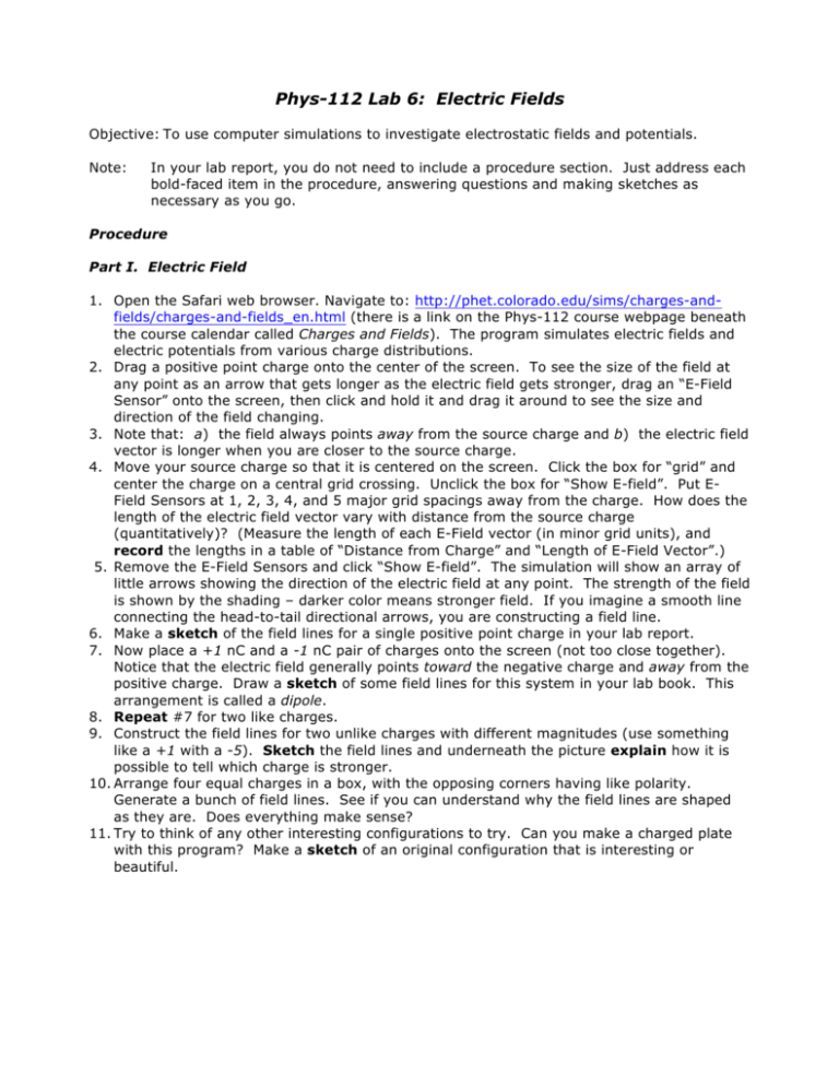
Phys-112 Lab 6: Electric Fields Objective: To use computer simulations to investigate electrostatic fields and potentials. Note: In your lab report, you do not need to include a procedure section. Just address each bold-faced item in the procedure, answering questions and making sketches as necessary as you go. Procedure Part I. Electric Field 1. Open the Safari web browser. Navigate to: http://phet.colorado.edu/sims/charges-andfields/charges-and-fields_en.html (there is a link on the Phys-112 course webpage beneath the course calendar called Charges and Fields). The program simulates electric fields and electric potentials from various charge distributions. 2. Drag a positive point charge onto the center of the screen. To see the size of the field at any point as an arrow that gets longer as the electric field gets stronger, drag an “E-Field Sensor” onto the screen, then click and hold it and drag it around to see the size and direction of the field changing. 3. Note that: a) the field always points away from the source charge and b) the electric field vector is longer when you are closer to the source charge. 4. Move your source charge so that it is centered on the screen. Click the box for “grid” and center the charge on a central grid crossing. Unclick the box for “Show E-field”. Put EField Sensors at 1, 2, 3, 4, and 5 major grid spacings away from the charge. How does the length of the electric field vector vary with distance from the source charge (quantitatively)? (Measure the length of each E-Field vector (in minor grid units), and record the lengths in a table of “Distance from Charge” and “Length of E-Field Vector”.) 5. Remove the E-Field Sensors and click “Show E-field”. The simulation will show an array of little arrows showing the direction of the electric field at any point. The strength of the field is shown by the shading – darker color means stronger field. If you imagine a smooth line connecting the head-to-tail directional arrows, you are constructing a field line. 6. Make a sketch of the field lines for a single positive point charge in your lab report. 7. Now place a +1 nC and a -1 nC pair of charges onto the screen (not too close together). Notice that the electric field generally points toward the negative charge and away from the positive charge. Draw a sketch of some field lines for this system in your lab book. This arrangement is called a dipole. 8. Repeat #7 for two like charges. 9. Construct the field lines for two unlike charges with different magnitudes (use something like a +1 with a -5). Sketch the field lines and underneath the picture explain how it is possible to tell which charge is stronger. 10. Arrange four equal charges in a box, with the opposing corners having like polarity. Generate a bunch of field lines. See if you can understand why the field lines are shaped as they are. Does everything make sense? 11. Try to think of any other interesting configurations to try. Can you make a charged plate with this program? Make a sketch of an original configuration that is interesting or beautiful. Part II. Electric Potential 1. Now place a single +1 charge onto a grid point. Remove the E-Field Sensors and unclick “Show E-field” to turn off the arrows. Click on the meter with the cross-hairs and move it around to measure the potential for any point on the screen. Measure the potential at several grid points. How does the potential vary with distance from the source? Do you notice any unexpected values? Can you explain them? 2. Place the charge at a grid crossing, and measure the voltage at several grid units distant. Make a table with distance (measured in number of boxes) and voltage. In Pasco Capstone, make a graph of Potential versus Distance. See if you can fit a curve to the function. Include a copy of Sketch the graph with the fitted curve in your report. 3. Measure some values for a -1 charge. How are the values different from those for a +1 charge? 4. Position the crosshairs various distances from the charge and click “plot”. This will generate some equipotential lines. Then turn on the E-Field lines to generate some electric field lines. Notice that field lines are always perpendicular to equipotential lines. 5. Repeat #4 with two like charges, two unlike charges, and some more complex multiple charge systems. Make a sketch of the equipotentials for two like point charges and two unlike point charges. Make a sketch of any other interesting multiple charge systems you discover. Part III: Electric Field Hockey 1. Close the browser. In the dock on the computer desktop (next to the trash), click on the file electric-hockey_en.jnlp to run the Electric Field Hockey program. In this program you try to use positive and negative point charges to maneuver a charge around obstacles and into a goal. Work through the instructions at the beginning to see how it works. 2. Play around with the game. See if you can get through at least the first two levels. (There are three possible levels on your way to the coveted “Coulomb Cup.”) In your lab books, sketch the setup for each level you completed, including the charges you placed and the path the charge took on the way to the goal. Note: you may NOT re-size the program window to open up space outside the obstacles. You need to maneuver through the obstacles, not around them. 3. Bonus: Get extra credit! Win the Coulomb Cup for completing all three levels. Print out the completed page after level three and include it in your report. Questions 1. What is the physical meaning of electric field lines? 2. Explain why it makes sense that potentials are positive for positive charges and negative for negative charges. Remember that a test charge is positive. 3. What is the physical interpretation of the fact that electric field lines are always perpendicular to equipotential lines?
