I N S TA L L AT I O N
f o o t b o a r d e x t e n d e r s 450
Fi t s : ’ 9 2 - u p Roa d Ki ngs and Dressers. W ill not work on models equ ipped
wi t h H- D P / N 9 9 0 02-97 — “ Chrome Displ ay S tand”
INSTALLATION QUESTIONS
techsupport@kuryakyn.com
or call 715.247.2983
Parts Included
1
3
2
3
1
Spacer Plate — Six Holes
1/2” I.D. Round Spacer
5/16”–18 x 1-3/4” H.H.C.S. — Stainless Steel
1/2”–13 x 1-3/4” S.H.C.S. — Stainless Steel
Installation Instructions
LIMITED WARRANTY
Please read and understand entire instructions before starting installation.
Thank you for choosing Küryakyn!
Küryakyn warrants that any Küryakyn products sold
hereunder, shall be free of defects in materials and
workmanship for a period of one (1) year from the
date of purchase by the consumer excepting the following provisions:
• Küryakyn shall have no obligation in the event
the customer is unable to provide a receipt showing
the date the customer purchased the product(s).
• The product must be properly installed,
maintained and operated under normal conditions.
PLEASE NOTE
It is the installers’ responsibility to make sure all fasteners (including pre-assembled) are
tightened before operation of motorcycle. Küryakyn will not warranty components that are
lost due to improper installation. Periodic maintenance may be required.
Tools Suggested
1/2” Combination and socket wrenches, 3/8” Allen wrench, Bike lift, or blocks to hold bike
upright without kickstand
Procedure
Step 1 Place the bike on a suitable stand, or block the bike up securely so the kickstand
will not be required.
RIGHT SIDE:
Step 2 Remove the footboard with the mounting brackets as a unit. A 3/8” Allen wrench
or Allen socket will be required. Remove the large split lock washers from the stock bolts and
set them aside as they will be re-used.
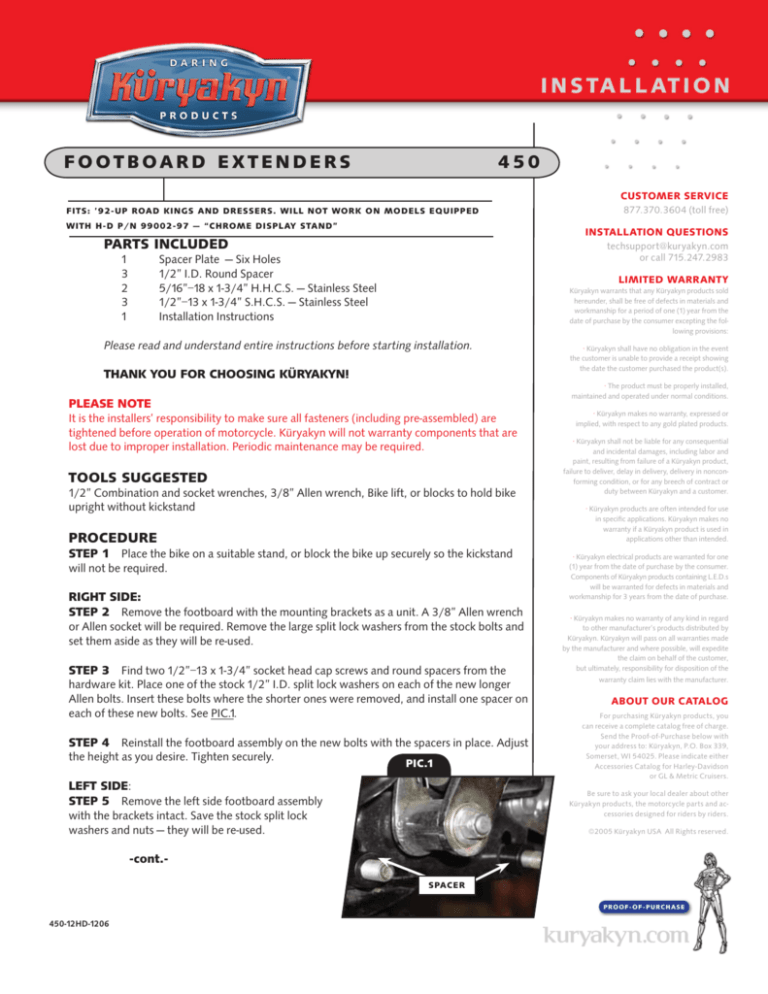
Step 3 Find two 1/2”–13 x 1-3/4” socket head cap screws and round spacers from the
hardware kit. Place one of the stock 1/2” I.D. split lock washers on each of the new longer
Allen bolts. Insert these bolts where the shorter ones were removed, and install one spacer on
each of these new bolts. See PIC.1.
Step 4 Reinstall the footboard assembly on the new bolts with the spacers in place. Adjust
the height as you desire. Tighten securely.
CUSTOMER SERVICE
877.370.3604 (toll free)
PIC.1
LEFT SIDE:
Step 5 Remove the left side footboard assembly
• Küryakyn makes no warranty, expressed or
implied, with respect to any gold plated products.
• Küryakyn shall not be liable for any consequential
and incidental damages, including labor and
paint, resulting from failure of a Küryakyn product,
failure to deliver, delay in delivery, delivery in nonconforming condition, or for any breech of contract or
duty between Küryakyn and a customer.
• Küryakyn products are often intended for use
in specific applications. Küryakyn makes no
warranty if a Küryakyn product is used in
applications other than intended.
• Küryakyn electrical products are warranted for one
(1) year from the date of purchase by the consumer.
Components of Küryakyn products containing L.E.D.s
will be warranted for defects in materials and
workmanship for 3 years from the date of purchase.
• Küryakyn makes no warranty of any kind in regard
to other manufacturer’s products distributed by
Küryakyn. Küryakyn will pass on all warranties made
by the manufacturer and where possible, will expedite
the claim on behalf of the customer,
but ultimately, responsibility for disposition of the
warranty claim lies with the manufacturer.
ABOUT OUR CATALOG
For purchasing Küryakyn® products, you
can receive a complete catalog free of charge.
Send the Proof-of-Purchase below with
your address to: Küryakyn, P.O. Box 339,
Somerset, WI 54025. Please indicate either
Accessories Catalog for Harley-Davidson®
or GL & Metric Cruisers.
Be sure to ask your local dealer about other
Küryakyn products, the motorcycle parts and accessories designed for riders by riders.
with the brackets intact. Save the stock split lock
washers and nuts — they will be re-used.
©2005 Küryakyn USA® All Rights reserved.
-cont.Spacer
PROOF-OF -PURCHASE
450-12HD-1206
Step 6 See PIC.2. Replace the original 1/2”–13 Allen bolt with one of the new longer ones included.
The stock split lock washer will be re-used. Place the remaining spacer on this bolt as shown.
Step 7 See PIC.3. Position the spacer plate as shown using the included 5/16”–18 x 1-3/4” hex head
bolts and stock split lock washers, installed from the rear with the threads facing outward.
PIC.2
Step 8 Reinstall the footboard and bracket assembly in the same manner as it was
removed. The stock 5/16” nut will be reused. Adjust as desired. Tighten securely.
Note
On some models, the 5/16”-18 x 1-3/4” hex heads bolt, stock split washer will be
installed from the outside. See PIC.4.
Spac e r
Ride On!
PIC.4
PIC.3
Spac e r
p l at e
Page
2
footboard extenders
INSTALLATION


