Continuous machining of a 0.1-mm diameter through hole into
〜〜 Machining network created with MITSUBISHI 〜〜
Machining technology News
Continuous Boring of φ 0.1 mm Holes Penetrated through Stainless Steel
This newsletter demonstrates how the micro milling machine μ V1 can be used to bore small diameter through holes to meet the needs in manufacturing various nozzles for chemical industrial use. Since such applications are highly demanding particularly in terms of hole shape and pitch accuracy, it is essential to reduce the runout of the tool in order to perform accurate positioning.
Workpiece material SUS316
Machining shape
Machine used
Machining shape φ 0.1mm
Plate thickness: 1 mm
Continuous boring of 50 holes
μ V1
Machining Conditions
μV1
Process Tool
Spindle speed min -1
Feed rate mm/min
(mm/rev)
Step amount mm
Center hole, chamfering
φ 0.2 coated cemented carbide micro center drill 15,000 1 (0.00007) ―
Boring φ 0.1 coated cemented carbide micro drill 15,000 3 (0.0002) 0.005
(1)Through hole boring is prone to tool breakage when the drill is removed. To deal with this problem, our original drilling cycle macro* was used to lower the machining conditions when the drill is removed.
* This macro, created using standard G-code, can be used to set the machining conditions that are applied when the drill is inserted and removed, respectively.
(2) To ensure that thin workpieces can be clamped without distortion, we used a vacuum chuck to machine them along with sub plates.
(3) The coolant we used was water insoluble oil coolant.
Machining Results
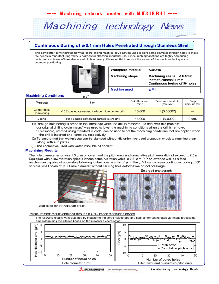
The hole diameter error was 1.5 μ m or lower, and the pitch error and cumulative pitch error did not exceed ± 2.5
μ m.
Equipped with a low vibration spindle whose actual vibration value is 0.5 μ m P-P or lower as well as a feed mechanism capable of accurately following instructions in units of μ m, the μ V1 can achieve continuous boring of 50 or more small holes of φ 0.1 mm diameter without causing hole deformation or tool breakage.
Enlarged photograph
Sub plate for the vacuum chuck
・ Measurement results obtained through a CNC image measuring device
The following results were obtained by measuring the bored hole shape and hole center coordinates via image processing and determining the pitches based on the measured coordinates:
10 10
5 5
0 0
-5
-10
0 10 20 30
Number of bored holes
40
Hole diameter error
50
-5
-10
0
Pitch error
Cumulative pitch error
10 20 30 40
Number of bored holes
Pitch error and cumulative pitch error
50
Manufacturing Technology Center

