Strain Gage Installation
advertisement
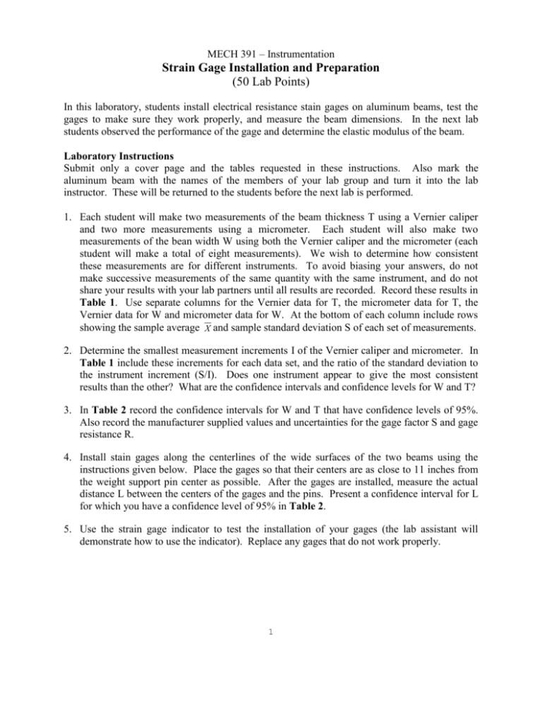
MECH 391 – Instrumentation Strain Gage Installation and Preparation (50 Lab Points) In this laboratory, students install electrical resistance stain gages on aluminum beams, test the gages to make sure they work properly, and measure the beam dimensions. In the next lab students observed the performance of the gage and determine the elastic modulus of the beam. Laboratory Instructions Submit only a cover page and the tables requested in these instructions. Also mark the aluminum beam with the names of the members of your lab group and turn it into the lab instructor. These will be returned to the students before the next lab is performed. 1. Each student will make two measurements of the beam thickness T using a Vernier caliper and two more measurements using a micrometer. Each student will also make two measurements of the bean width W using both the Vernier caliper and the micrometer (each student will make a total of eight measurements). We wish to determine how consistent these measurements are for different instruments. To avoid biasing your answers, do not make successive measurements of the same quantity with the same instrument, and do not share your results with your lab partners until all results are recorded. Record these results in Table 1. Use separate columns for the Vernier data for T, the micrometer data for T, the Vernier data for W and micrometer data for W. At the bottom of each column include rows showing the sample average X and sample standard deviation S of each set of measurements. 2. Determine the smallest measurement increments I of the Vernier caliper and micrometer. In Table 1 include these increments for each data set, and the ratio of the standard deviation to the instrument increment (S/I). Does one instrument appear to give the most consistent results than the other? What are the confidence intervals and confidence levels for W and T? 3. In Table 2 record the confidence intervals for W and T that have confidence levels of 95%. Also record the manufacturer supplied values and uncertainties for the gage factor S and gage resistance R. 4. Install stain gages along the centerlines of the wide surfaces of the two beams using the instructions given below. Place the gages so that their centers are as close to 11 inches from the weight support pin center as possible. After the gages are installed, measure the actual distance L between the centers of the gages and the pins. Present a confidence interval for L for which you have a confidence level of 95% in Table 2. 5. Use the strain gage indicator to test the installation of your gages (the lab assistant will demonstrate how to use the indicator). Replace any gages that do not work properly. 1 Surface Preparation 1. 2. 3. 4. 5. Degrease the surface using CSM-1 Degreaser and gauze sponge. Abrade the surface with silicon-carbide paper wetted with Conditioner A. Scratch reference lines into the surface with a ballpoint pen. Scrub the surface with Conditioner A and a cotton swab. Dry with a gauze sponge. Scrub the surface with Neutralizer 5A and cotton swab. Dry with a gauze sponge. Strain Gage Bonding 1. Place the strain gage and terminal in position (1/16 inches apart) on a clean surface and fasten them in place with clear tape. 2. Lift the tape at a shallow angle to avoid over-stressing gage. 3. Position the gage over reference lines and tape it down. 4. Lift the tape to expose the strain gage, leaving one end of tape anchored to surface. 5. Brush M-Bond Catalyst lightly onto the strain gage and let dry. 6. Apply one or two drops of M-Bond 200 Adhesive to the junction of tape and surface. 7. Holding the tape taut, wipe the strain gage onto surface. 8. Apply firm pressure to gage with your thumb for one minute. 9. Allow the adhesive to dry for two additional minutes. 10. Remove the tape. 11. Cut a red/black/white wire approximately 12 inches long. 12. Solder red wire to one junction/terminal, black and white wires to another 13. Read the expected strain gage resistance using free ends of wires (make sure it works) 14. Apply rosin solvent to the solder joints. Remove the solvent with a gauze sponge. 15. Coat the gage, terminal, and wires with M-Coat A. Operating Procedures for Digital Strain Indicator 1. Hook the wires to strain indicator using quarter bridge configuration: red wire goes to the red terminal, white to the white terminal, and black to the yellow D120 terminal. 2. Set the BRIDGE button to ¼. 3. Set the MULT button to X1. 4. Depress the AMP ZERO button. Set the AMP ZERO control to 0000. 5. Depress the GAGE FACTOR button. Set GAGE FACTOR range switch and GAGE FACTOR control to effective gage factor listed on back of strain gage package (2.110). 6. Depress the RUN button. Set the BALANCE switch and BALANCE control to 0000. 7. Depress the CAL button. Set the GAGE FACTOR control to calibration number. Calibration number = (2.000/pkg. Gage factor)x500 = 4739. 8. Depress the RUN button and verify that the strain gage works by slightly bending specimen in both directions. 2
