Force Measurement: Load Cells & Torque Measurement
advertisement
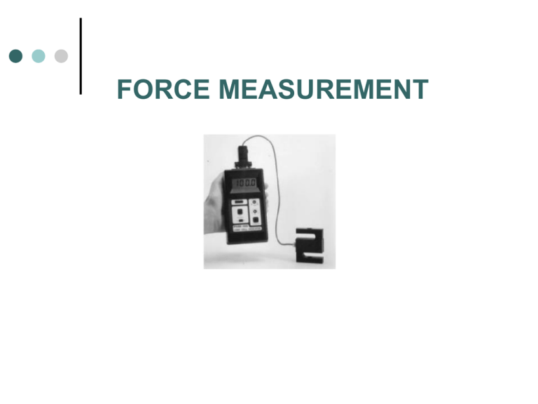
FORCE MEASUREMENT INTRODUCTION •TRANSDUCERS THAT MEASURE FORCE AND TORQUE USUALLY CONTAIN AN ELASTIC MEMBER THAT CONVERTS THE MECHANICAL QUANTITY TO A DEFLECTION OR STRAIN (IS CALLED LOAD CELL) •A DEFLECTION SENSOR (FOR EXAMPLE, STRAIN GAGE) IS THEN USED TO GIVE AN ELECTRICAL SIGNAL PROPORTIONAL TO THE QUANTITY OF INTEREST (FORCE OR TORQUE) •RANGE, LINEARITY AND SENSITIVITY ARE DETERMINED BY THE SIZE AND SHAPE OF THE ELASTIC MEMBER, THE MATERIAL USED AND THE SENSOR LOAD CELLS The elastic members commonly used in load cells are links, beam, rings, and shear web LINK TYPE LOAD CELL P Wheatstone bridge strain gage 3(axial) on the back face strain gage 4 (transverse) strain gage 2 (transverse) For full bridge arrangement R3 R4 V o R 2 R 3 R1 R 4 strain gage 1 (axial) R1 R1 R2 P R2 R3 R3 R4 R4 GF . a GF . GF . t GF . P V s Vo R 3 R1 R 2 R 4 ( R 2 R 3 ) R 3 R1 R2 R4 V s R2 R3 2 If R1=R2=R3=R4 AE P AE Vo GF . P (1 )V s 2 AE EXAMPLE A strip of high strength steel has a length of 30 cm and a cross section of 20 mm by 20 mm. The modulus of elasticity is 200 GPa, and Poisson’s ratio is 0.27. It is subjected to an axial load of 15000 N and it is instrumented with full bridge arrangement of strain gage with R=120 W and gage factor of 2.10. Determine output voltage if a supply voltage of 2.5 V is applied. Solution : Use equation Vo GF . P (1 )V s 2 AE BEAM TYPE LOAD CELL Beam type load cells are commonly employed for measuring low-level loads where the link type load cell is too stiff to be effective P x 1 2 3 4 6M Ebh 2 6 Px Ebh 2 1 h 3 R1 R1 R2 R2 R3 R3 R4 R4 6 GF . Px Ebh 2 b Vo axial gage 1 and 3 axial gage 2 and 4 on the bottom surface R 3 R1 R 2 R 4 ( R 2 R 3 ) R 3 R1 R2 R4 V s R2 R3 2 If all strain gage are identical Vo R 3 R1 R 2 R 4 ( R 2 R 3 ) R 3 R1 R2 R4 V s R2 R3 2 V0 6 GF . P . x .V s Ebh 2 TORQUE MEASUREMENT (TORQUE CELLS) Torque cells are transducers that convert an applied torque to an electrical output signal. V xy 1 TD 2J 16 T D 3 16 T 1 16 T 1 , 2 3 3 D E D E For circular shaft subjected to pure torsion, all normal stress are 0, the principal stress s1=s2=xz Principal strain R1 R1 R2 R2 R3 R3 R4 R4 16 T 1 3 D E .GF V0 16 T 1 3 D E GF .V s MECHANICAL POWER MEASUREMENT (DYNAMOMETER) END OF LECTURE
