- JPE-Journal of Power Electronics
advertisement
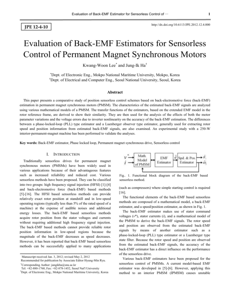
Evaluation of Back-EMF Estimator for Sensorless Control of … 1 http://dx.doi.org/10.6113/JPE.2012.12.4.000 JPE 12-4-10 Evaluation of Back-EMF Estimators for Sensorless Control of Permanent Magnet Synchronous Motors Kwang-Woon Lee* and Jung-Ik Ha† * Dept. of Electronic Eng., Mokpo National Maritime University, Mokpo, Korea Dept. of Electrical and Computer Eng., Seoul National University, Seoul, Korea † Abstract This paper presents a comparative study of position sensorless control schemes based on back-electromotive force (back-EMF) estimation in permanent magnet synchronous motors (PMSM). The characteristics of the estimated back-EMF signals are analyzed using various mathematical models of a PMSM. The transfer functions of the estimators, based on the extended EMF model in the rotor reference frame, are derived to show their similarity. They are then used for the analysis of the effects of both the motor parameter variations and the voltage errors due to inverter nonlinearity on the accuracy of the back-EMF estimation. The differences between a phase-locked-loop (PLL) type estimator and a Luenberger observer type estimator, generally used for extracting rotor speed and position information from estimated back-EMF signals, are also examined. An experimental study with a 250-W interior-permanent-magnet machine has been performed to validate the analyses. Key words: Back-EMF estimator, Phase locked loop, Permanent magnet synchronous drive, Sensorless control I. INTRODUCTION Traditionally sensorless drives for permanent magnet synchronous motors (PMSMs) have been widely used in various applications because of their advantageous features such as increased reliability and reduced cost. Various sensorless methods have been proposed. They can be classified into two groups: high frequency signal injection (HFSI) [1]-[4] and back-electromotive force (back-EMF) based methods [5]-[16]. The HFSI based sensorless methods can provide relatively exact rotor position at standstill and in low-speed operating regions (typically less than 5% of the rated speed of a machine) at the expense of audible noises and additional energy losses. The back-EMF based sensorless methods acquire rotor position from the stator voltages and currents without requiring additional high frequency signal injection. The back-EMF based methods cannot provide reliable rotor position information in low-speed regions because the magnitude of the back-EMF decreases as speed decreases. However, it has been reported that back-EMF based sensorless methods can be successfully applied to many applications Manuscript received Jan. 3, 2012; revised May 2, 2012 Recommended for publication by Associate Editor Hyung-Min Ryu. † Corresponding Author: jungikha@snu.ac.kr Tel: +82-880-1760, Fax: +82-878-1452, Seoul Nat'l University * Dept. of Electronic Eng., Mokpo National Maritime University, Korea Fig.. 1. Functional block diagram of the back-EMF based sensorless method. (such as compressors) where simple starting control is required [16]. The functional elements of the back-EMF based sensorless methods are composed of a mathematical model, a back-EMF estimator, and a speed/position estimator, as shown in Fig. 1. The back-EMF estimator makes use of stator command voltages (v*), stator currents (i), and a mathematical model of the PMSM to derive the back-EMF signals. The rotor speed and position are observed from the estimated back-EMF signals by means of another estimator such as a phase-locked-loop (PLL) type estimator or a Luenberger type state filter. Because the rotor speed and position are observed from the estimated back-EMF signals, the accuracy of the back-EMF estimator has a direct influence on the performance of the sensorless drive. Various back-EMF estimators have been proposed for the sensorless control of PMSMs. A current model-based EMF estimator was developed in [5]-[6]. However, applying this method to an interior PMSM (IPMSM) causes unstable 2 Journal of Power Electronics, Vol. 12, No. 4, July 2012 sensorless operation, as the assumptions adopted in the model of the IPMSM are not valid in all operating ranges. To solve this problem, the extended EMF model was proposed in [7]. The extended EMF model includes saliency terms, as well as the back-EMF, so that the simplifying assumptions made to the model are not necessary. In [7] and [8], an extended EMF model in the stationary reference frame was used for sensorless control. The extended EMF estimated in the stationary reference frame is in an AC form. Therefore, some phase delay between the actual and the estimated EMF is inevitable, as the estimator is a filter and filters have an intrinsic phase delay. The extended EMF model in the rotor reference frame provides the position error instead of the rotor position. However, the phase delay is negligible in this case, because the extended EMF in the rotor reference frame is a DC signal [9]. Model-based back-EMF estimators are sensitive to motor parameter variations, back-EMF harmonics, and voltage errors in the inverter [10]-[12]. The harmonics due to the nonlinearity of the inverter is the main cause of degradation of performance in back-EMF based sensorless drives at low speeds; a smaller gain for a back-EMF estimator is required to expand the lower operating range [10]. Voltage error compensation methods were used in [10]-[11] to reduce the negative effects of the inverter harmonics on a back-EMF estimator. The deviation of the motor parameters caused by magnetic saturation and thermal change also degrades the performance of back-EMF based sensorless drives. Online parameter identification is an alternative to motor parameter variations [12]-[13]. This paper evaluates three kinds of back-EMF estimators (a proportional-integral (PI) type state filter [8], a disturbance observer type estimator [9], [14], and a reduced-order observer [15]) based on the extended EMF model in the rotor reference frame. The transfer functions of back-EMF estimators are derived and the similarities among the back-EMF estimators are demonstrated based on their transfer functions. The effects of parameter variations and inverter harmonics on the accuracy of back-EMF estimation are investigated in detail using the derived transfer function and its bode-plot. These analyses explain why the resistance and the q-axis inductance variation have a greater influence on the back-EMF estimation accuracy than other parameters. The phase-locked-loop (PLL) type estimator and the Luenberger type estimator are commonly utilized to extract the rotor speed and position from the estimated back-EMF signals. The differences between these two estimators are also examined. To prove the validity of the analyses performed in this paper, experimental results obtained with an IPMSM drive are provided. α-β and d-q frames represent the stationary and the rotor Fig. 2. Space vector diagram of PMSM [9]. reference frames, respectively. The α axis corresponds to the magnetic axis of the u phase and the d axis is aligned with the direction of the N pole of the rotor. The γ-δ frame is an estimated frame used in sensorless vector control using the rotor reference frame. r and ˆr are the actual and estimated rotor positions, respectively. A. Mathematical Model in the Stationary Reference Frame The PMSM voltage equation in the stationary reference frame is: pL1 sin 2 r v R pL0 L1 cos 2 r i v pL1 sin 2 r R pL0 L1 cos 2 r i (1) sin r r PM cos r where: vα , vβ stator voltage in the stationary α - β frame; iα , iβ stator current in the stationary α - β frame; stator resistance; R p differential operator; λPM permanent magnet flux linkage; ωr rotor angular velocity; θr rotor position; Ld Lq Ld Lq L0 , L1 , 2 2 Ld and Lq are the d- and q-axes inductances. The second term on the right-hand side of (1) is the back-EMF and it includes the rotor position information. In the case of a surface mounted PMSM (SPMSM), Ld and Lq are identical, Ld = Lq = Ls. Thus equation (1) can be simplified as follows: 0 i e v R pLs (2) v 0 R pLs i e where: II. MATHEMATICAL MODEL OF A PMSM FOR BACK-EMF ESTIMATION Fig. 2 shows a space vector diagram for a PMSM [9]. The e sin r . e r PM cos r (3) In a SPMSM, eα and eβ , the back-EMF signals in the stationary frame can be easily estimated using a simple estimating strategy and equation (2). However, for the Evaluation of Back-EMF Estimator for Sensorless Control of … IPMSM, it is difficult to construct the back-EMF observer using equation (1) owing to the unknown parameter 2θr, which is caused by the machine saliency. The extended EMF model, presented in [7], can simplify the voltage equation for an IPMSM as follows: r Ld Lq i v R pLd sin r (4) v L L R pL i Eex cos r d q d r where Eex is the extended EMF, and is defined by (5): (5) Eex r [( Ld Lq )id PM ] ( Ld Lq )( piq ) . The second term on the right-hand side of (4) corresponds to eα and eβ. The rotor position can be calculated directly using (6): eˆ (6) ˆr tan 1 ( ) eˆ where ˆr is the estimated rotor position, and ê and ê are the back-EMF signals estimated in the stationary reference frame using (2) or (3). However, ê and ê are AC signals. Therefore, a phase delay exists between the actual and the estimated back-EMF signals due to the intrinsic phase delay of the back-EMF estimator. This effect results in some rotor position estimation error. As a result, the special phase delay compensation method is generally required. B. Mathematical Model in the Rotor Reference Frame The voltage equation of the PMSM in the rotor reference frame is given by: vd R pLd r Lq id 0 . (7) v L R pLq iq r PM q r d The voltage equation of the PMSM in the γ - δ frame is derived as follows [9]: v R pLd r Lq i sin r PM v L (8) R pL i q cos r d i i i L a p r Lb ˆ r r L c i i i where Δθ is the position error between the γ-δ and the d-q reference frame, ̂r is an estimated rotor angular speed, and Ld Lq sin 2 La Ld Lq sin cos Ld Lq sin cos Lb 2 Ld Lq sin L L sin cos Lc d 2 q 2 Ld sin Lq cos L d Lq sin cos 2 d Lq sin L (9) Ld Lq sin 2 (10) Ld Lq sin cos Lq cos 2 Lq sin 2 .(11) Ld Lq sin cos Equation (8) is too complicated to be useful in building an estimator. However, for a SPMSM, Ld = Lq = Ls, and thus equation (8) can be simplified as follows: r Ls i sin r PM R pLs i cos i ˆ r r Ls . i v R pLs v L r s 3 (12) To simplify the voltage equation of an IPMSM in the γ-δ reference frame, the extended EMF can also be applied to the rotor reference frame model as follows [7], [9]: i v R pLd r Lq i e (ˆ r r ) Ld (13) v L R pLd i e r q i where: e sin . e Eex cos (14) The second term on the right-hand side of (13) is the back-EMF. However, the back-EMF in the γ-δ reference frame includes the rotor position error, rather than the rotor position. This is the difference between the stationary and the rotor reference frame models. Under the steady-state condition, it is possible to ignore the third term on the right-hand side of (13) because the error between ̂r and r is sufficiently small and equation (13) can be simplified using (15): v R pLd r Lq i e . (15) v L R pLd i e r q The estimated rotor position error ˆ can be calculated using (16): ˆ tan 1 ( where ê eˆ ) eˆ (16) and ê are the back-EMF signals estimated using (15) in the γ-δ reference frame. When using the rotor reference frame model, the estimated back-EMF signals are DC values. Therefore, the phase delay between the actual and the estimated signals is negligible. This is the advantage of the rotor reference frame model when compared to the stationary reference frame model. On the other hand, an additional rotor position estimator is required for the rotor reference frame model because the rotor position error (Δθ) is estimated instead of the rotor position (θr). In addition, the third term in (13), ignored in (15), may generate a back-EMF estimation error in the transient-state condition, where the error between ̂ r and r is no longer negligible. III. ANALYSIS OF THE BACK-EMF ESTIMATOR The back-EMF signals can be estimated using either the α-β or the γ-δ reference frame model. This paper focuses on the analysis of back-EMF estimators based on the extended-EMF model in the γ-δ reference frame, because the phase delay in the back-EMF estimator is relatively small when compared to that in the α-β reference frame model. 4 Journal of Power Electronics, Vol. 12, No. 4, July 2012 A. Back-EMF Estimator Using PI Type State Filter The PI type back-EMF estimator presented in [8] can also be implemented in the γ - δ reference frame model as shown in Fig. 3. In Fig. 3, R̂ , L̂d , and L̂q are the nominal motor parameters, kp and ki are the proportional and integral gains of the state filter, respectively, and i is a stator current vector, which can be expressed as follows: i i ji (17) where iγ and iδ are the stator currents in the γ-δ reference Fig. 3. Back-EMF estimator using PI type state filter. frame. î , v * , and Ê correspond to the estimated stator current vector, the commanded voltage vector, and the estimated back-EMF vector in the γ-δ reference frame, respectively, and can be expressed in an equation similar to (17). The estimated back-EMF in Fig. 3 is given by (18): ˆ E (k p s k i )( Lˆ d s Rˆ ) ˆ Ld s 2 (k p Rˆ ) s k i E v * jˆ r Lˆ q i Ld s R Lˆ d s Rˆ v j r Lq i j ˆ r r Ld i Ld s R Fig. 4. Back-EMF estimator using disturbance observer. back-EMF estimator using the disturbance observer is implemented using both a low-pass filter and a high-pass filter as follows: (18) The gains of the PI type back-EMF estimator are selected by using the pole-zero cancellation method as follows: (22) ˆ ˆ ˆ est Ld s R E E s est Ld s R (19) where ωest is the bandwidth of the back-EMF estimator. By substituting (19) into (18), the following is obtained: . The estimated EMF using the disturbance observer is given by (23): where v is the voltage vector in the γ-δ reference frame. ˆ ˆ ˆ est Ld s R E est v* jˆ Lˆ i E r q s est Ld s R s est s est Lˆd i s est k p Lˆd est , ki Rˆ est ˆ v* jˆ Lˆ i Rˆ i est E r q s est (20) Lˆ s Rˆ v jr Lqi j ˆ r r Ld i d Ld s R . By assuming that the errors in the motor parameters, the voltage vector, and the estimated speed are sufficiently small, the transfer function of the back-EMF estimator, shown in Fig. 3, is derived as follows: Ê est . (21) E s est From (21), it is clear that the characteristics the PI type back-EMF estimator are the same as those of a first-order low-pass filter. B. Back-EMF Estimator Using a Disturbance Observer Fig. 4 shows a back-EMF estimator using a disturbance observer [9]. A differential operator is included in Fig. 4. To minimize the negative effects of the differential operation, the est v * jˆ r Lˆq i s est (23) Lˆd s Rˆ v j r Lq i j ˆ r r Ld i . Ld s R From (20) and (23), it is evident that the back-EMF estimator using the disturbance observer is the same as the PI type back-EMF estimator. Therefore, the bandwidth of the low-pass filter in Fig. 4 also determines the bandwidth of the transfer function from the actual back-EMF to the estimated back-EMF. C. Back-EMF Estimator Using a Reduced Order Observer By assuming that the sampling frequency is sufficiently high and that the back-EMF is constant during a sampling period, the dynamic equations of a PMSM based on the extended EMF model are given as follows: i R d i 1 r Lq dt e Ld 0 e 0 1 v 0 v Ld 0 Ld 0 r Lq R 0 0 0 1 0 0 1 0 i 0 1 i 0 0 e 0 0 e (24) Evaluation of Back-EMF Estimator for Sensorless Control of … 5 then the estimated back-EMF is given by (34): ˆ ˆ ˆ est Ld s R E E s est Ld s R Fig. 5. Back-EMF estimator using the reduced order observer. i i 1 0 0 0 i y . i 0 1 0 0 e e (25) iγ and iδ, which are the stator currents in the γ-δ reference frame, are measurable. New output variables are defined using the measurable state variables as follows: y new 1 e Ld e (26) r Lq v R i i i L L L d d d . r Lq v R 1 e i i i L L Ld Ld d d Using (26), the reduced observer can be follows: 1 1 eˆ L1 e eˆ Ld Ld r Lq v L R 1 eˆ L1 i i i Ld Ld Ld Ld constructed as (27) 1 1 r q (34) Lˆd s Rˆ v jr Lqi j ˆ r r Ld i . Ld s R Thus, the three kinds of back-EMF estimators based on the extended EMF model in the γ-δ reference frame have the same operating characteristics, although the back-EMF estimators have a different structure. D. Analysis of the Back-EMF Estimation Error The back-EMF estimator uses a mathematical model of a PMSM and the commanded voltage. Therefore, the accuracy of the back-EMF estimator is directly affected by the motor parameter variations and the voltage errors due to inverter nonlinearities. To analyze the effects of parameter variations and voltage errors on the accuracy of the back-EMF estimator, the nominal motor parameters must be examined, and the rotor angular speed and the commanded voltages must be estimated as follows: Rˆ R R , Lˆ L L , Lˆ L L (35) d d q (32) To implement the observer from (31) and (32), the estimated rotor angular speed and the commanded voltages are used, instead of the actual rotor angular speed and voltages. Fig. 5 shows a back-EMF ( êr ) estimator designed using (29) and (31). The value of ê can be also estimated using a similar method, as shown in Fig. 5. The gains of the reduced observer should be selected as: (33) L1 L2 Lˆd est , q q ˆ r r r , v vr vr , v v v * (30) 2 e L2i . Using the new state variables, η1 and η2 , the observer can be designed as follows: L L (31) ̂ 1 ˆ 1 L R i L i v Ld Ld L L ̂ 2 2 ˆ 2 2 L2 R i r Lq i v . Ld Ld est v* jˆ r Lˆq i s est d 1 1 eˆ L2 e eˆ Ld Ld (28) r Lq v L2 R eˆ L2 i i i Ld Ld Ld Ld where L1 and L2 are the observer gains. To remove the differential terms in (27) and (28), new state variables, η1 and η2 , are defined as follows: (29) 1 e L1i 1 * (36) where ΔR, Δ Ld , and ΔLq are the errors between the nominal and the actual motor parameters, Δωr is the estimated rotor speed error, and Δvγ and Δvδ are the voltage errors due to inverter nonlinearities. Using (34), (35) and (36), the following is obtained: est Lˆ s Rˆ eˆ d e s est Ld s R (37) est Ld s R est v 1 v1 s est Ld s R s est est Lˆ s Rˆ eˆ d e s est Ld s R (38) est Ld s R est v 1 v 2 s est Ld s R s est where v 1 v r Lq i , v 1 v r Lq i v L i L i L i L i . v1 v r Lq i r Lq i Lq i Ld i v2 r q r q q d Under the steady state condition, Δωr is sufficiently small that Δv1 and Δv2 can be simplified as follows: v1 v r Lq i (39) v2 v r Lqi . (40) Δv1 and Δv2 are functions of Δvγ, Δvδ, and ΔLq. Δvγ and Δvδ are the voltage errors due to inverter nonlinearities. They consist mainly of 6-th order harmonics and their frequency is proportional to the rotor speed. From equations (37) to (40), it 6 Journal of Power Electronics, Vol. 12, No. 4, July 2012 Fig. 7. PLL type speed and position estimator [9]. (a) and from vγ1 to the estimated γ axis back-EMF, as shown in Fig. 6. Three combinational cases of motor parameter deviations are considered in the bode plots. To allow better estimation of the back-EMF, the gain of the transfer function from the actual back-EMF to the estimated back-EMF should be close to 0 dB and that of the transfer function from vγ1 to eγ should be decreased as much as possible. In Fig. 6, it can bee seen that the accuracy of the back-EMF estimator is more sensitive to stator resistance errors than to d-axis inductance errors. IV. SPEED AND POSITION ESTIMATORS A. PLL Type Speed and Position Estimators The PLL type speed and position estimator shown in Fig. 7 is generally used to acquire the estimated rotor speed and position from the estimated rotor position error. The PI controller for Ge(s) in Fig. 7, which is generally used, is given as follows: Ge ( s ) K ep K ei s (41) and the transfer function from ˆr to ˆr1 is given by (42): (b) Fig. 6. Bode plots of the transfer functions (a) from the actual γ axis back-EMF to the estimated γ axis back-EMF and (b) from vγ1 to the estimated γ axis back-EMF (R = 5.8Ω, Ld = 0.11126H, ωest = 100Hz). can be seen that the estimated EMFs are affected by Δvγ and Δvδ via the low-pass filter. Thus the effects of Δvγ and Δvδ on the estimated EMF decrease as ωr increases, because the 6th order harmonics are attenuated by the low-pass filter. On the other hand, the effects of ΔLq on the estimated EMF increase as ωr increases, because ΔLq is multiplied by ωr, as shown in the second term on the right side of (39) and (40). In addition, the second terms of (39) and (40) are not attenuated by the low-pass filter, as they are DC signals. Thus, the accuracy of the estimated EMF becomes more sensitive to ΔLq at high speeds, and it becomes more sensitive to voltage errors at low speeds. To improve the accuracy of the back-EMF estimator at low speeds, the bandwidth of the back-EMF estimator ωest should be decreased so as to further filter the undesirable voltage harmonics. Dead time compensation can be considered as an alternative method to improve the performance of the back-EMF estimator at low speeds. To analyze the effects of ΔR and ΔLd on the estimated EMF, consider the bode plots of the transfer functions from the actual γ axis back-EMF to the estimated γ axis back-EMF K s K ei . ˆr1 2 ep ˆ r s K ep s K ei (42) By assuming that the denominator of (42) is the same as the characteristic equation of the standard second-order system, Kep and Kei can be selected based on the damping ratio ζ and the undamped natural frequency ωn. The transient response of the PLL type estimator can be improved by adding a double integral term into Ge(s) as follows [9]: Ge (s) K1 K 2 s K3 s 2 (43) The transfer function from ˆr and ˆr1 is given by (44): ˆr1 K s 2 K s K3 . (44) 3 1 2 2 ˆr s K1s K 2 s K3 K1, K2, and K3 can also be selected by using the damping ratio (ζ) and the undamped natural frequency (ωn) [9]. Fig. 8 shows the bode plots of (42) and (44) where ζ and ωn are set to 1 and 50 rad/s, respectively. Because the phase delay decreases, as shown in Fig. 8, when the double integral term is added, it is natural that the performance of the double integral type estimator is improved in the transient state. B. Luenberger Observer Type Speed and Position Estimator A Luenberger observer type speed and position estimator can also be used for the estimation of rotor speed and Evaluation of Back-EMF Estimator for Sensorless Control of … 7 where J and B are the coefficients of the inertia and viscous friction, respectively, and Ĵ and B̂ are the nominal parameters. The gains of the estimator in (45) can be selected such that the characteristic equation of (45) has the same roots as the followings [17]: (46) K 3 , K 3Jˆ 2 , K Jˆ 3 1 2 3 where β is the root of the characteristic equation. To construct a Luenberger observer type speed and position estimator, the mechanical parameters J and B are required, whereas a PLL type estimator does not require the use of mechanical parameters. It is possible to obtain zero phase lag with the use of a Luenberger observer type estimator with accurate machine parameters [8]. However, this estimator is sensitive to the inertia parameter error and its structure is more complex than that of a PLL type estimator. Also, the PLL type estimator can filter high frequency noise included in the estimated position error, because its frequency response is the same as that of the low-pass filter, as shown in Fig. 8. Fig. 8. Bode plots of PLL type estimators. V. Fig. 9. Luenberger observer type speed and position estimator. [8], [17]. position, as shown in Fig. 9 [8],[17]. The transfer function of the Luenberger observer type position estimator, shown in Fig. 9, is given by (45): ˆr1 Js3 ( B JˆK1 )s 2 ( Bˆ K1 K 2 )s K 3 (45) 3 Jˆs ( Bˆ JˆK ) s 2 ( Bˆ K K )s K ˆ r 1 Fig. 10. Experimental test setup. 1 2 3 EXPERIMENTAL RESULTS To verify the effectiveness of the analyses of the back-EMF estimators, experiments were performed using a 250-W IPMSM coupled to a permanent-magnet DC (PMDC) load motor, as shown in Fig. 10. The parameters of the tested IPMSM are listed in Table I. The DC-links of each inverter for the tested IPMSM and the PMDC motor are connected together so that additional equipment for processing the regenerative energy from the PMDC motor is not required. The back-EMF based sensorless algorithms are implemented on a Texas Instruments TMS320F28335 floating-point digital signal processor (DSP). The switching frequency of the inverter is 10 kHz and the dead-time is 3 μs. The sampling period is 1 ms for the speed control and 0.1ms for the current control, the sensorless speed and the position estimation. The bandwidth of the current controller is 100 Hz. An encoder with a resolution of 1,024 pulses per revolution (PPR) is used to monitor the actual rotor position. 8 Journal of Power Electronics, Vol. 12, No. 4, July 2012 TABLE I 250-W IPMSM NOMINAL PARAMETERS Base speed R Ld Lq λPM Poles 3200 rpm 5.8 Ω 0.11126 H 0.165 H 0.159 Wb 6 A. The Stationary Reference Frame Model Case To examine the characteristics of the back-EMF estimator using the stationary reference frame model, experiments were performed using the PI type back-EMF estimator presented in [8]. Fig. 11 and Fig. 12 show the experimental results when the bandwidth of the PI type back-EMF estimator is chosen to be 300Hz. A constant load torque of 0.55 N·m is applied during sensorless operation. The estimated rotor position in Fig. 12 is directly calculated using (6). In Fig. 12, it can be seen that some phase delay exists between the measured and the estimated rotor position. This is because the estimated back-EMF signals are AC signals, as shown in Fig. 11. The phase delay in the back-EMF estimator is unavoidable. The phase delay between the actual and the estimated back-EMF increases as the rotor speed increases. If the bandwidth of the back-EMF estimator is increased so as to reduce the phase delay, the back-EMF estimator becomes sensitive to inverter noises. Thus, an additional phase delay compensation method is required for the back-EMF estimator in the stationary reference frame model. B. The Rotor Reference Frame Model Case Fig. 13 and Fig. 14 show the transient and steady-state responses when the PI type back-EMF estimator using the rotor reference frame model, shown in Fig. 3, is used. The bandwidth of the back-EMF estimator is chosen to be 100 Hz. The rotor speed and position are estimated through the PLL type speed and position estimator shown in Fig. 7. The PI controller in the PLL type estimator is set to ζ =1 and ωn=50 rad/s. The PI controller of (41) and (43) were used to produce the signals shown in Fig. 13 and Fig. 14, respectively. To examine the transient-state response according to the structure of the PI controller in the PLL type estimator, the load torque was changed from 50% (0.37 N·m) to 100% (0.73 N·m) while the motor was running at 1000 rpm. From Fig. 12 and Fig. 14, it can be seen that the transient-state performance of (43) is better than that of (41). This corresponds with the analysis in Fig. 8. When using the rotor reference frame model, the steady-state error between actual and the estimated rotor position is small when compared to that in the stationary reference frame model. This is because the estimated back-EMFs in the rotor reference frame model are DC signals. Therefore, the steady-state phase delay in the back-EMF estimator is negligible. Experiments on the disturbance observer type back-EMF estimator shown in Fig. 4 and the reduced-order observer type back-EMF estimator shown in Fig. 5 show the same results as Fig. 13 and Fig. 14 under the same conditions. The effect of motor parameter errors on the back-EMF Fig. 11. Estimated current and extended EMF at rotor speed = 1000 rpm. Fig. 12. Steady-state estimated position at rotor speed = 1000 rpm. Fig. 13. Position estimated with PI-type PLL at rotor speed = 1000 rpm. estimation error can be monitored via the estimated rotor position error, because the rotor position is estimated from the estimated back-EMF. Fig. 15, Fig. 16, and Fig. 17 show the estimated rotor position error when the nominal stator resistance and the nominal d-q axes inductances vary from 70% to 130% of their nominal values (listed in Table I) while the motor is running at 5%, 10%, 20%, and 30% of the rated speed (3200 rpm) with a 100% load (0.73 N·m). From these figures, it can be seen that the difference between the maximum and the minimum values of the estimated rotor position error decrease as the rotor speed increases. This result occurs because the voltage errors due to inverter nonlinearities are filtered through the low-pass filter included in the back-EMF estimator. Also, it can be observed that the estimated rotor position errors are more sensitive to the nominal q-axis inductance error. This coincides with the analyses presented in this paper. Evaluation of Back-EMF Estimator for Sensorless Control of … Fig. 14. Position estimated with lead-lag compensator-type PLL at rotor speed = 1000 rpm. 9 (d) Fig. 15. Estimated position error versus nominal stator resistance variation at rated load with constant speed ( (a) 5%, (b) 10%, (c) 20%, and (d) 30% of rated speed). (a) (a) (b) (b) (c) (c) 10 Journal of Power Electronics, Vol. 12, No. 4, July 2012 (d) Fig. 16. Estimated position error versus nominal d-axis inductance variation at rated load with constant speed ( (a) 5%, (b) 10%, (c) 20%, and (d) 30% of rated speed). (d) Fig. 17. Estimated position error versus nominal q-axis inductance variation at rated load with constant speed ( (a) 5%, (b) 10%, (c) 20%, and (d) 30% of rated speed). VI. CONCLUSIONS (a) (b) (c) This paper has analyzed several back-EMF estimators for the sensorless control of a PMSM and verified the effectiveness of these analyses through experimental studies. The following points summarize the work presented in this paper. 1) When using the stationary reference frame model, a phase delay between the actual and the estimated back-EMF exists, because the back-EMFs in the stationary reference frame are AC signals. On the other hand, the phase delay is negligible when using the rotor reference frame model, because the estimated EMFs are DC signals. 2) There are three kinds of back-EMF estimators based on the rotor reference frame model, which include the PI type, the disturbance observer type, and the reduced observer type estimator. They all have the same transfer function and the same operating characteristics. 3) The effects of the motor parameter errors and the voltage errors due to inverter nonlinearities on the back-EMF estimation error were analyzed and verified through experiments. The voltage errors are filtered by the low-pass filter included in the back-EMF estimator. The back-EMF estimation error due to voltage errors decreases as the rotor speed increases. To reduce the back-EMF estimation error at low speeds, the bandwidth of the back-EMF estimator should be decreased or a dead-time compensator can be used. The back-EMF estimator error is more sensitive to the q-axis inductance error because the voltage errors due to the q-axis inductance error increase as the rotor speed increases and they are not filtered through the low-pass filter included in the back-EMF estimator. Thus an additional q-axis inductance error compensation method is required for stable operation of the sensorless control at high speed. Bode plots of the transfer function from the actual to the estimated back-EMF show that the stator resistance error can also decrease the accuracy of the estimated back-EMF. Evaluation of Back-EMF Estimator for Sensorless Control of … REFERENCES [1] P. L. Jansen and R. D. Lorenz, “Transducerless position and velocity estimation in induction and salient AC machines,” IEEE Trans. Ind. Applicat., Vol. 31, No. 2, pp. 240-247, Mar./Apr. 1995. [2] M. Corley and R. Lorenz, “Rotor position and velocity estimation for salient-pole permanent magnet synchronous machine at standstill and high speed,” IEEE Trans. Ind. Applicat., Vol. 34, No. 4, pp. 784-789, July/Aug. 1998. [3] M. W. Degner and R. D. Lorenz, “Using multiple saliencies for the estimation of flux, position, and velocity in AC machines,” IEEE Trans. Ind. Applicat., Vol. 34, No. 5, pp. 1097-1104, Sep./Oct. 1998. [4] J. Ha, K. Ide, T. Sawa, and S. Sul, "Sensorless rotor position estimation of an interior permanent-magnet motor from initial states," IEEE Trans. Ind. Applicat., Vol. 39, No. 3, pp. 761-767, May/Jun. 2003. [5] N. Matsui, T. Takeshita, and K. Yasuda, “A new sensorless drive of brushless DC motor,” in Proc. IECON '92, pp. 430-435, 1992. [6] N. Matsui, “Sensorless PM brushless DC motor drives,” IEEE Trans. Ind. Electron., Vol. 43, No. 2, pp. 300-308, Apr. 1996. [7] Z. Chen, M. Tomita, S. Ichikawa, S. Doki, and S. Okuma, “Sensorless control of interior permanent magnet synchronous motor by estimation of an extended electromotive force,” in Conf. Rec. IEEE-IAS Annu. Meeting, Vol. 3, pp. 1814-1819, Oct. 2000. [8] H. Kim, M. C. Harke, and R. D. Lorenz, “Sensorless control of interior permanent-magnet machine drives with zero-phase lag position estimation,” IEEE Trans. Ind. Applicat., Vol. 39, No. 6, pp. 1726-1733, Nov./Dec. 2003. [9] S. Morimoto, K. Kawamoto, M. Sanada, and Y. Takeda, “Sensorless control strategy for salient-pole PMSM based on extended EMF in rotating reference frame,” IEEE Trans. on Ind. Applicat., Vol. 38, No. 4, pp. 1054-1061, Jul./Aug. 2002. [10] R. W. Hejny, and R. D. Lorenz, “Evaluating the practical low-speed limits for back-EMF tracking-based sensorless speed control using drive stiffness as a key metric,” IEEE Trans. on Ind. Applicat., vol. 47, pp. 1337–1343, May/Jun. 2011. [11] Y. Inoue, Y. Kawaguchi, S. Morimoto, and M. Sanada, “Performance improvement of sensorless IPMSM drives in a low-speed region using online parameter identification,” IEEE Trans. Ind. Applicat., Vol. 47, No. 2, pp. 798-804, Mar./Apr. 2011. [12] Y. Inoue, K. Yamada, S. Morimoto, and M. Sanada, “Effectiveness of voltage error compensation and parameter identification for model based sensorless control of IPMSM,” IEEE Trans. Ind. Applicat., Vol. 45, No. 1, pp. 213-221, Jan./Feb. 2009. [13] S. Ichikawa, M. Tomita, S. Doki, and S. Okuma, “Sensorless control of synchronous reluctance motors based on extended EMF models considering magnetic saturation with online parameter identification,” IEEE Trans. Ind. Applicat.., Vol. 42, No. 5, pp. 1264-1274, Sep./Oct. 2006. [14] M. Tomita, T. Senjyu, S. Doki, and S. Okuma, “New sensorless control for brushless DC motors using disturbance observers and adaptive velocity estimations,” IEEE Trans. Ind. Electron., Vol. 45, No. 2, pp. 274-282, Apr. 1998. [15] J. Kim and S. Sul, “High performance PMSM drives without rotational position sensors using reduced order 11 observer,” in Conf. Rec. IEEE-IAS Annu. Meeting, pp. 75-82, 1995. [16] B.-H. Bae, S.-K. Sul, J.-H. Kwon, and J.-S. Byeon, "Implementation of sensorless vector control for super-high-speed PMSM of turbo-compressor," IEEE Trans. on Ind. Applicat., Vol. 39, No. 3, pp. 811-818, May/June, 2003. [17] S.-K. Sul, Control of Electric Machine Drive Systems, John Wiley & Sons, New Jersey, 2011. Kwang-Woon Lee was born in Seoul, Korea. He received his B.S., M.S., and Ph.D. in Electrical Engineering from Korea University, Seoul, Korea, in 1993, 1995, and 1999, respectively. From 2000 to 2002, he was with Samsung Advanced Institute of Technology, Yongin, Korea, where he worked on the development of micro-electromechanical system sensor applications. From 2002 to 2007, he was a Senior Research Engineer with the Samsung Living Appliance R&D Center, Samsung Electronics, Suwon, Korea, where he was engaged in research on sensorless motor drive systems for refrigerators and air conditioners. He is currently an Assistant Professor in the Department of Electronic Engineering, Mokpo National Maritime University, Mokpo, Korea. His current research interests include power electronics and control, which include ac machine drives, digital-signal-processing-based control applications, and fault diagnosis of electrical machines. Jung-Ik Ha was born in Korea in 1971. He received his B.S., M.S., and Ph.D. in Electrical Engineering from Seoul National University, Seoul, Korea, in 1995, 1997, and 2001, respectively. From 2001 to 2002, he was a Researcher for the Yaskawa Electric Co., Japan. From 2003 to 2008, he worked for Samsung Electronics Co., Korea as a Senior and Principal Engineer. From 2009 to 2010, he was a Chief Technology Officer for LS Mechapion Co., Korea. Since 2010, he has been an Assistant Professor in the School of Electrical Engineering, Seoul National University. His current research interests include the circuits and control of high efficiency integrated electric energy conversion in various industrial fields.

