International Journal of Science, Engineering and Technology Research (IJSETR)
Volume 1, Issue 1, May 2014
Proposal of Wastewater Treatment Process and
Design for Soap Industry
Su Sundy Maung, Tin Tin Htwe
Abstract - This study presents the wastewater treatment
plant for soap industry. Soap industry generates relatively large
quantities of wastewater that may contain various potentially
organic matters. Therefore, the proper management of
industrial wastewater is essential. The quality and quantity of
wastewater from this industry are studied and the suitable
method for wastewater treatment system is considered. The
wastewater from soap industry is collected for three times and
analysed at the laboratory of ISO TECH in Yangon (Myanmar).
Physical, chemical and biological parameters of wastewater are
measured. Then, the results are compared into public sewer of
Indian Standards. According to the experimental results, the
concentrations of pH, suspended solids, BOD, COD are higher
than acceptable level of Indian Standards. The wastewater
production from the soap industry is 595000 l/day with the BOD
content of 43000 mg/l and COD content of 99200 mg/l. Based on
the test results and wastewater discharge, there are two
proposes of wastewater treatment plant in the study. The first
propose is wastewater treatment including neutralization basin,
upflow anaerobic sludge blanket, alum dosing, flocculation,
primary settling, activated sludge process and final
sedimentation tank. After passing the treatment plant, the
effluent BOD, COD and suspended solids are 347 mg/l, 3456
mg/l and 430 mg/l. Alternatives propose includes screening,
alum dosing, flocculation, primary sedimentation tank, trickling
filter, aeration tank and secondary sedimentation tank with
effluent BOD (347 mg/l). The result values of two methods are
less than the acceptable BOD quality of 350 mg/l for discharging
into public sewer.
Industries consumes huge amount of fresh water, depleting a
valuable resource required for everyday human activities. In
addition, wastewater effluents loaded with pollutants often pose
significant hazards to the environment. It is therefore important to
have high-performance and low-cost wastewater treatment plants to
treat and reuse industrial effluents. The strength of the wastewater is
determined by measuring the amount of suspended material in the
water and the amount of organic material in the water.
If the industrial wastewater is thrown away without any treatment,
there will be much pollution to the environment. Due to this
condition, treatment plant is essentially needed from the aspect of
public health. The objective of this study is to reduce wastewater
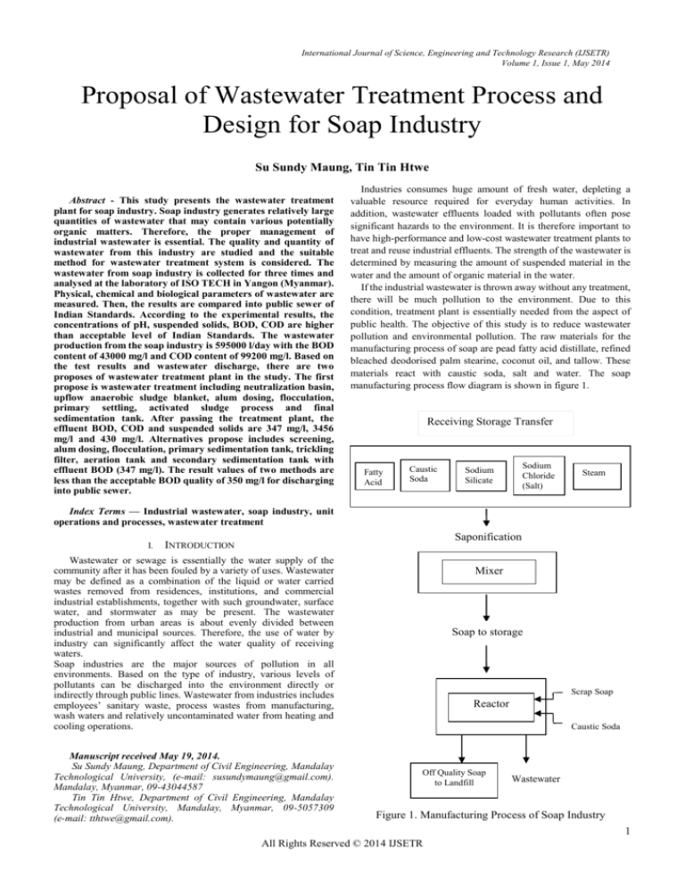
pollution and environmental pollution. The raw materials for the
manufacturing process of soap are pead fatty acid distillate, refined
bleached deodorised palm stearine, coconut oil, and tallow. These
materials react with caustic soda, salt and water. The soap
manufacturing process flow diagram is shown in figure 1.
Receiving Storage Transfer
Fatty
Acid
Caustic
Soda
Sodium
Chloride
(Salt)
Sodium
Silicate
Steam
Index Terms — Industrial wastewater, soap industry, unit
operations and processes, wastewater treatment
I.
Saponification
INTRODUCTION
Wastewater or sewage is essentially the water supply of the
community after it has been fouled by a variety of uses. Wastewater
may be defined as a combination of the liquid or water carried
wastes removed from residences, institutions, and commercial
industrial establishments, together with such groundwater, surface
water, and stormwater as may be present. The wastewater
production from urban areas is about evenly divided between
industrial and municipal sources. Therefore, the use of water by
industry can significantly affect the water quality of receiving
waters.
Soap industries are the major sources of pollution in all
environments. Based on the type of industry, various levels of
pollutants can be discharged into the environment directly or
indirectly through public lines. Wastewater from industries includes
employees’ sanitary waste, process wastes from manufacturing,
wash waters and relatively uncontaminated water from heating and
cooling operations.
Manuscript received May 19, 2014.
Su Sundy Maung, Department of Civil Engineering, Mandalay
Technological University, (e-mail: susundymaung@gmail.com).
Mandalay, Myanmar, 09-43044587
Tin Tin Htwe, Department of Civil Engineering, Mandalay
Technological University, Mandalay, Myanmar, 09-5057309
(e-mail: tthtwe@gmail.com).
Mixer
Soap to storage
Scrap Soap
Reactor
Caustic Soda
Off Quality Soap
to Landfill
Wastewater
Figure 1. Manufacturing Process of Soap Industry
1
All Rights Reserved © 2014 IJSETR
International Journal of Science, Engineering and Technology Research (IJSETR)
Volume 1, Issue 1, May 2014
II. WASTEWATER CHARACTERISTICS
Wastewater is characterized in terms of its physical,
chemical, and biological composition. The physical, chemical
and biological examinations are performed to know the
wastewater characteristics.
A. Total Solids
The total solids in a wastewater consist of the insoluble or
suspended solids and the soluble compounds dissolved in
water. The suspended solids content is found by drying and
weighing the residue removed by the filtering of the sample.
When this residue is ignited the volatile solids are burned off.
Between 40 and 65 % of the solids in an average wastewater
are suspended. Settleable solids, expressed as miligram per
litre, are those that can be removed by sedimentation [1].
B. Colour
Colour is a qualitative characteristic that can be used to
assess the general condition of wastewater. Wastewater that is
light brown in colour is less than 6 h old, while a
light-to-medium grey colour is characteristic of wastewaters
that have undergone some degree of decomposition or that
have been in the collection system for some time [1].
C. Odour
The determination of odour has become increasingly
important, as the general public has become more concerned
with the proper operation of wastewater treatment facilities.
The odour of fresh wastewater is usually not offensive, but a
variety of odorous compounds are released when wastewater
is decomposed biologically under anaerobic conditions [1].
D. Temperature
The measurement of temperature is important because
most wastewater treatment schemes include biological
processes that are temperature dependent. In addition, oxygen
is less soluble in warm water than in cold water [1].
E. Alkalinity
Alkalinity in wastewater results from the presence of the
hydroxide, carbonates, and bicarbonates of elements such as
calcium, magnesium, sodium, potassium, or ammonia [1].
The alkalinity in wastewater helps to resist changes in pH
caused by the addition of acids.
F. Dissolved Oxygen
Dissolved oxygen is required for the respiration of aerobic
microorganisms as well as all other aerobic life forms.
However, oxygen is only slightly soluble in water [4].
G. Biological Oxygen Demand (BOD)
Biological oxygen demand (BOD) is the quantity of
oxygen used by microorganisms in the aerobic stabilization of
wastewaters and polluted waters. The standard 5-day BOD
value is commonly used to define the strength of wastewaters,
to evaluate the efficiency of treatment by measuring oxygen
demand remaining in the effluent, and to determine the
amount of organic pollution in surface waters [5].
H. Chemical Oxygen Demand (COD)
The chemical oxygen demand (COD) of wastewater or
polluted water is a measure of the oxygen equivalent of the
organic matter susceptible to oxidation by a strong chemical
oxidant. The organic matter destroyed by the mixture of
chromic and sulphuric acids is converted to CO2 and water.
The COD test is also used to measure the organic matter in
industrial and municipal wastes that contain compounds that
are toxic to biological life [2].
The results of soap wastewater characteristics are shown
in table I. The test results are described that they contain
highest pollutents such as BOD, COD, suspended solids and
total solids.
TABLE I. RESULTS OF WASTEWATER ANALYSIS
Results
Unit
1st
Time
2nd
Time
3rd
Time
Into
Public
Sewers of
Indian
Standard
Temperature
̊C
25.5
25
24.5
45
Chemical
Oxygen
Demand
(COD)
mg/l
128000
101000
99200
10000
Biological
Oxygen
Demand
(BOD)
mg/l
51200
48200
43000
350
Dissolved
Oxygen (DO)
mg/l
3.8
4.2
5.4
-
pH
-
14
13.6
11.2
5.50-9.00
Colour (True)
TCU
2200
1800
1200
-
Turbidity
NTU
8230
7920
6320
-
Total
Hardness
mg/l as
CaCO3
12800
11620
10600
-
Total
Alkalinity
mg/l as
CaCO3
9200
9000
7880
-
Phosphate
mg/l
1.8
1.00
0.8
-
Chloride (Cl)
mg/l
16400
16220
12860
1000
Sulphate (SO4)
mg/l
13200
12800
10010
1000
Total Solids
mg/l
59200
59900
50380
2700
Suspended
Solids
mg/l
12800
11100
10080
600
Dissolved
Solids
mg/l
59200
48800
40300
2100
Characteristics
III.
TREATMENT METHOD
Wastewater treatment objectives are based primarily on
aesthetic and environmental concerns. The objectives of
reduction and removal of BOD, suspended solids and
pathogenic micro-organisms continued but at higher levels.
The degree of treatment can be determined by comparing the
influent wastewater characteristics to the required effluent
wastewater characteristics. A number of different treatment
and disposal or reuse alternatives are then developed and
evaluated, and the best alternative is selected.
Wastewater treatment is a combination of physical,
chemical, and biological processes. Methods of treatment in
which the application of physical forces predominate are
known as unit operations while methods of treatment in which
chemical or biological activities are involved are known as
2
All Rights Reserved © 2014 IJSETR
International Journal of Science, Engineering and Technology Research (IJSETR)
Volume 1, Issue 1, May 2014
unit processes. There are three types of unit operations and
processes: 1. Physical unit operations, 2. Chemical unit
processes, and 3. Biological unit processes.
A. Physical Unit Operation
Treatment methods in which the applications of physical
forces predominate are known as physical unit operations.
Because most of these methods evolved directly from man's
first observations of nature, they were the first to be used for
wastewater treatment. Screening, mixing, flocculation,
sedimentation, flotation, filtration, and gas transfer are typical
unit operations [5].
B. Chemical Unit Processes
Chemical unit processes are those in which removal of
contaminants are brought about by chemical activity. In the
field of wastewater treatment, chemical unit operations are
usually used in conjunction with physical unit operations and
biological unit processes. Precipitation, absorption, and
disinfection are the most common examples used in
wastewater treatment [5].
C. Biological Unit Processes
Biological unit processes are those in which removal of
contaminants are brought about by biological activity. In
biological treatment of wastewater, the objectives are to
coagulate and remove the non-settleable colloidal solids and
to stabilize the organic matter. Basically, these substances are
converted into gases that can escape to the atmosphere and
into biological cell tissue that can be removed by settling [5].
In order to treat wastewater, it is necessary to know the
function of treatment process.
i. Collection Tank
In this study, storage tank is considered as tank on ground
with concrete.
ii. Screening
The first step in wastewater treatment is the removal or
reduction of coarse solids. The usual procedure is to pass the
untreated wastewater through bar racks or screens. A screen is
a device with openings, generally of uniform size, that is used
to retain the coarse solids found in wastewater. The screening
element may consists of parallel bars, rods or wires, grating,
wire mesh, perforated plate, and the openings may be of any
shape but generally are circular or rectangular slots. The
materials removed by these devices are known as screening.
iii. Coagulation and Flocculation
Coagulation is employed for the removal of waste
materials in suspended or colloidal form. Colloids are
presented by particles over a size range of 1 nm (10-7 cm) to
0.1 nm (10-8 cm). These particles do not settle out on standing
and cannot be removed by conventional physical treatment
processes. Coagulation reduces the net electrical repulsive
forces at particle surfaces by adding coagulant chemicals,
whereas flocculation is agglomeration of the destabilized
particles by chemical joining and bridging.
In wastewater treatment, coagulation and flocculation are
used to destabilize turbidity, color, odor-producing
compounds, pathogens, and other contaminants in surface
waters. Flocculation is agitation of chemically treated water to
induce coagulation. In this manner, very small suspended
particles collide and agglomerate into larger heavier floc that
settles out by gravity. Flocculation is a principal mechanism
in removing turbidity from water.
iv. Primary Sedimentation Tank
The objective of treatment by sedimentation is to remove
readily settleable solids and floating and thus reduce the
suspended-solids content. Sedimentation is the removal of
solids particles from suspension by gravity. In water
treatment, the common application of sedimentation is after
chemical treatment to remove flocculated impurities and
precipitates. In wastewater processing, sedimentation is used
to reduce suspended solids in the influent wastewater and to
remove settleable solids after biological treatment.
v. Trickling Filter
Trickling filters are used for biological treatment of
domestic sewage and industrial wastes which are amenable to
aerobic biological processes. Trickling filters, also known as
percolating filters or sprinkling filters are similar to contact
beds in construction, but their operation is continuous and
they allow constant aeration. The trickling filter is always
preceded by primary sedimentation along with skimming
devices to remove the scum. This will prevent the clogging of
the filter by settleable solids. The effluent from the filter is
then taken to secondary sedimentation tanks for settling out
organic solids oxidized while passing through the filter.
vi. Activated Sludge Process
The activated sludge is the sludge which is obtained by
settling sewage in presence of abundant oxygen so as to be
supercharged with favourable aerobic micro-organisms. The
activated sludge process of sewage treatment is based on
providing intimate contact between the sewage and biological
active sludge.
The effluent from the primary settling tank is mixed with a
dose of activated sludge and is aerated in an aeration tank for
a period of some hours. During the aeration, the
micro-organisms in the sewage multiply by assimilating part
of the influent organic matter. In this process, part of organic
matter is synthesized into new cells and part is oxidized to
derive energy. The synthesis reaction, followed by subsequent
separation of the resulting biological mass and the oxidation
reaction are the main mechanisms of BOD removal in the
activated sludge process.
The biomass is generally flocculant and quick settling. It is
separated from the aerated sewage in a secondary settling tank
and is recycled continuously to the aeration tank as an
essential feature of the process. The BOD removal is
evaluated based on the BOD5 of the aeration tank influent and
the BOD5 of the final effluent after sludge separation. The
3
All Rights Reserved © 2014 IJSETR
International Journal of Science, Engineering and Technology Research (IJSETR)
Volume 1, Issue 1, May 2014
viii. Upflow Anaerobic Sludge Blanket (UASB)
Anaerobic decomposition involves in the breakdown of
organic wastes to gas (methane and carbon dioxide) in the
absence of oxygen. The quantity of organic matter converted
to gas will vary from 80 to 90 percent.
In the upflow anaerobic sludge blanket wastewater is
directed to the bottom of the reactor where it must be
distributed uniformly. The wastewater flows upward through
a blanket of biologically formed granules which consume the
waste as it passes through the blanket. Methane and carbon
dioxide gas bubbles rise and are captured in the gas dome.
Liquid passes into the settling portion of the reactor where
solids-liquid separation takes place. The solids return to the
blanket area while the liquid exists over the wires. To keep the
blanket in suspension, an upflow velocity of 2 to 3 ft/h (0.6 to
0.9 m/h) has been used.
IV. PROPOSAL AND DESIGN OF WASTEWATER TREATMENT
PLANT
Depending on the constituents that must be removed, an
almost limitless number of different flowsheet can be
developed using unit operations and processes. In the study,
there are two types of proposed flowsheet for soap wastewater
treatment.
In order to design wastewater treatment plant, it is
necessary to determine the design discharge. In this study, the
discharge from soap wastewater is considered for the
treatment plant. According to wastewater generation
standards, 1 kilogram (1kg) of soap produces 23.4L of
wastewater. The soap production per day is 25424 kg.
Therefore, wastewater flow rate from soap industry is 595
m3/day.
A. Proposal 1
Based on the characteristics of soap wastewater, the
appropriate treatment process such as neutralization,
anaerobic process, alum dosing and flocculation, primary
settling, activated sludge processes are chosen and designed
according to their respective design criteria to obtain the
acceptable wastewater quality of into public sewers Indian
Standards. In secondary treatment, activated sludge process
(suspended growth process) is used. In this process includes
aeration tank, secondary clarifier and returned sludge line.
The proposal 1 for the treatment plant of soap industry is
shown in figure 2.
Raw
w/w
Collection
Tank
Alum
Neutralization
Basin
UASB
Coagulation
&
Flocculation
Primary
Sedimentation
Tank
Recirculation
effluent is of high quality, usually having a lower BOD than
that of a trickling filter. The BOD removal is up to 80-95
percent and the degree of bacteria removal is up to 90-95
percent.
vii. Neutralization
Many industrial wastes contain acidic or alkaline materials
that require neutralization prior to discharge to receiving
waters or prior to chemical or biological treatment. For
biological treatment, a pH in the biological system should be
maintained between 6.5 and 8.5 to ensure optimum biological
activity. The biological process itself provides a
neutralization and a buffer capacity as a result of the
production of CO2, which reacts with caustic and acidic
materials. The degree of preneutralization required depends,
therefore, on the ratio of BOD removed and the causticity or
acidity present in the waste.
Aeration Tank
Sludge
Secondary
Sedimentation
Tank
Effluent
Figure 2. Proposal 1 for treatment plant of soap industry
i. Design of Collection and Neutralization Tank
Raw wastewater from the industry flows into the
collection tank. In this study, collection tank is considered as
tank on ground with concrete. For the design of the collection
tank, wastewater is stored for 1hrs. Dimension of tank is 2 m ×
8.5 m × 1.5 m. For the design of neutralization tank,
wastewater is passed for 6 minutes with the average air rate
(0.6 m3/min-m2). Dimension of tank is 1 m × 1 m × 2.5 m.
ii. Design of Upflow Anaerobic Sludge Blanket (UASB)
To keep the blanket in suspension, an upflow velocity of 2
to 3 ft/h (0.6 to 0.9 m/h) has been used with retention time (4
hours). Dimension of tank is 5 m diameter and 4.95 m depth.
After passing this tank, the effluent BOD and COD are 4300
mg/l with removal efficiency (90%) and 9920 mg/l with
removal efficiency (90%).
iii. Design of Alum Dosage Per Day
The required dosage of alum varies from 75mg/l – 250
mg/l depending upon the condition [2]. Chemical
precipitation (alum coagulant) can be removed from 40
to70% of BOD, 80 to 90% of suspended solids and 30 - 60 %
of COD. Considering for the average percentage removal, the
effluent BOD is obtained as 1720 mg/l, effluent suspended
solids is 1512 mg/l and effluent COD is 5456 mg/l . Alum is in
4
All Rights Reserved © 2014 IJSETR
International Journal of Science, Engineering and Technology Research (IJSETR)
Volume 1, Issue 1, May 2014
v. Design of Primary Sedimentation Tank
Sedimentation tanks are designed to reduce the velocity of
flow so as to permit suspended solids to settle out of water by
gravity. In this study, the circular shaped primary
sedimentation tank is used radically flow. Dimension of tank
is 4.5 m diameter and 3 m depth with detention time (2 hours).
The effluent BOD, COD and SS become 1118 mg/l, 3546
mg/l and 403 mg/l respectively.
vi. Design of Aeration Tank
It is a biological treatment process in which biologically
activated mass, called activated sludge is continuously mixed
with the sewage flow in the aeration basin in the presence of
oxygen. The oxygen is supplied to the mixed liquor either by
diffused compressed air or by mechanical aeration. In the
study, conventional activated sludge process is used.
Conventional activated sludge processes can be removed 80
to 95 % of BOD, 80 to 90 % of suspended solids, 80-85 % of
COD and 10- 25 % of phosphorus. Tank dimension is 6.5 m ×
38 m × 4.5 m. Total air required is 16 m3/min. Standard
diffuser plates of 0.3 m × 0.3 m × 25 mm passing 1.2 m3 of
air/m2 with pore sizes of 0.3 mm are chosen. Total number of
plates is 148 plates.
vii. Design of Secondary Sedimentation Tank
In conventional activated sludge process, the aeration tank
is followed by the secondary sedimentation tank. Tank
dimension is 4 m diameter and 4.5 m depth with detention
time (2.28 hours). The final effluent of BOD is 347 mg/l with
69 % removal efficiency.
B. Proposal 2
Alternative method of wastewater treatment plant is
considered. Based on the characteristics of soap wastewater,
the appropriate treatment process such as screening, alum
dosing and flocculation, primary settling, trickling filter,
aeration tank and secondary sedimentation tank are chosen
and designed according to their respective design criteria to
obtain the acceptable wastewater quality of into public sewers
Indian Standards. In secondary treatment, activated sludge
process (suspended growth process) is used. In this process
includes aeration tank, secondary clarifier and returned
sludge line. The proposal 2 for the treatment plant of soap
industry is shown in figure 3.
ii. Design of Screen
A screen is a device with openings generally of uniform
size. In this study, fine screen of rotary drum type is used and
designed according to the criteria. Dimension of drum screen
is 1.5 m diameter and 2.45 m length. The effluent of BOD and
SS are 34400 mg/l and 7812 mg/l.
Alum
Raw
w/w
Coagulation &
Flocculation
Collection
Tank
Primary
Sedimentation
Tank
Screen
Recirculation
iv. Design of Flocculation Tank
Flocculation is an essential operation designed to force
agitation in the fluid and induced coagulation. For the design
of flocculation tank, wastewater is passed for 30 minutes.
Dimension of tank is 4 m × 2 m × 1.5 m and provide revolving
paddles attached to two horizontal shafts tranverse to basin
length. Let each shaft should be located at mid depth of tank.
Let provide three paddles to each shaft. Paddle size is 0.03 m
wide and each of length 1 m with 31 watts of power
requirement.
i. Design of Collection Tank
Raw wastewater from the industry flows into the
collection tank. In this study, collection tank is considered as
tank on ground with concrete. For the design of the collection
tank, wastewater is stored for 1hrs. Dimension of tank is 2 m ×
8.5 m × 1.5 m.
Trickling Filter
Recirculation
more use than other coagulants because it is very cheap. It
reduces taste and odor in addition to turbidity. Alum required
per day is 59.5 kg/day.
Aeration Tank
Secondary
Sedimentation
Tank
Figure 3. Proposal 2 for Treatment Plant of Soap Industry
i. Calculation of Alum Dosage Per Day
Considering for the average percentage removal, the
effluent BOD is obtained as 13760 mg/l, effluent suspended
solids is 1172 mg/l and effluent COD is 54560 mg/l . Alum is
in more use than other coagulants because it is very cheap. It
reduces taste and odor in addition to turbidity. Alum required
per day is 59.5 kg/day.
ii. Calculation of Flocculation Tank
Flocculation is an essential operation designed to force
agitation in the fluid and induced coagulation. For the design
of flocculation tank, wastewater is passed for 30 minutes.
Dimension of tank is 4 m × 2 m × 1.5 m and provide revolving
paddles attached to two horizontal shafts tranverse to basin
length. Let each shaft should be located at mid depth of tank.
Let provide three paddles to each shaft. Paddle size is 0.03 m
wide and each of length 1 m.
iii. Design of Primary Sedimentation Tank
Sedimentation tanks are designed to reduce the velocity of
flow so as to permit suspended solids to settle out of water by
gravity. In this study, the circular shaped primary
sedimentation tank is used radically flow. Dimension of tank
is 4.5 m diameter and 3 m depth with detention time (2 hours).
5
All Rights Reserved © 2014 IJSETR
The effluent BOD, COD and SS become 8256 mg/l,
mg/l and 469 mg/l respectively.
International Journal of Science, Engineering and Technology Research (IJSETR)
Volume 1, Issue 1, May 2014
35464
ACKNOWLEDGMENT
iv. Design of High Rate Trickling Filter
In the first stage of secondary treatment, high rate trickling
filter is designed according to the criteria. Dimension of filter
is 37 m diameter and 3 m depth. The effluent BOD, COD and
SS are 1651 mg/l, 7092.8 mg/l and 117.25 mg/l respectively.
v. Design of Aeration Tank
Conventional activated sludge processes can be removed
80 to 95 % of BOD, 80 to 90 % of suspended solids, 80-85 %
of COD and 10- 25 % of phosphorus. Tank dimension is 6.5
m × 56 m × 4.5 m. Total air required is 27 m3/min. In this
process, mechanical aeration is used with paddle mechanism.
Provide revolving paddles attached to three horizontal shafts
running parallel to the length. Let each shaft should be located
at mid depth of tank. Let provide thirty paddles to each shaft.
Paddle size is 0.58 m wide and each of length 0.6 m with 4128
watts of power requirement.
vi. Design of Secondary Sedimentation Tank
In conventional activated sludge process, the aeration
tank is followed by the secondary sedimentation tank. Tank
dimension is 4 m diameter and 4.5 m depth with detention
time (2.28 hours). The final effluent of BOD is 347 mg/l with
79 % removal efficiency.
The author would like to express her heart felt gratitude to
Dr. Kyaw Moe Aung, Associate Professor and Head of Civil
Engineering
Department,
Mandalay
Technological
University. The author is deeply grateful to her supervisor Dr.
Tin Tin Htwe, Associate Professor, Department of Civil
Engineering, Mandalay Technological University, for her
valuable guidance, criticisms, encouragement comments,
suggestions and advice throughout the whole length of the
research work. The author would like to her gratefulness to all
people in soap industry (Mandalay). Finally, specially thanks
to her parents, for their moral support, patience,
understanding and encouragement.
REFERENCES
[1]
[2]
[3]
[4]
[5]
[6]
Metcalf & Eddy, third edition, “Wastewater Engineering Treatment,
Disposal, Reuses”, Tata McGraw-Hill Publishing Company Limited,
New Delhi, 1995.
W.Wesley Eckenfelder, Jr, second edition, 1989, “Industrial Wate
Pollution Control”, Tata McGraw-Hill Publishing Company Limited,
New
Lawrence K. Wang , 2006 by Taylor & Francis Group, “Treatment of
Soap and Detergent Industry Wastes”, The Cooper Union, New York,
U.S.A
Mark J Hammer Jr. fourth edition, “Water and Wastewater
Technology”, Prentic- Hall of India Private Limited, New Delhi,
2003.
“Environmental Engineering” for B.E course (Department of
Technical and Vocational Education)
“Environmental Engineering” for B.Tech course (Department of
Technical and Vocational Education )
V. DISCUSSION AND CONCLUSION
From the test result, the value of BOD, COD, suspended
solids and total dissolved solids are 43000 mg/l, 99200 mg/l,
10080 mg/l and 40300 mg/l respectively. These are high
content over the limit for public sewer of Indian Standard.
Based on the characteristics, the appropriate treatment
processes are chosen to design the soap wastewater treatment
plant. In the study, two types of treatment processes are
considered. In proposal 1 includes neutralization, anaerobic
process, alum dosing and flocculation, primary settling,
activated sludge processes. After passing through the
treatment process, the effluent of BOD, COD and SS become
347 mg/l, 3546 mg/l and 403 mg/l respectively. In proposal 2
includes screening, alum dosing and flocculation, primary
settling, trickling filter, aeration tank and secondary
sedimentation tank. After passing treatment plant, the effluent
BOD, COD and SS become 347 mg/l, 7092.8 mg/l and
117.25 mg/l respectively. The effluent BOD of two types of
treatment is the same with the value of 347 mg/l. But the
effluent COD of the first treatment process is lower than the
second. And then, neutralization basin is the reduction of
alkalinity for the soap wastewater. . Finally, the results of
effluent are within the BOD (350 mg/l), COD (10000 mg/l),
SS (600 mg/l) and dissolved solids (2100 mg/l) for disposal
into public sewer of Indian Standard.
6
All Rights Reserved © 2014 IJSETR


