Matrix of Worldwide Wireless Telecommunication Standard
advertisement
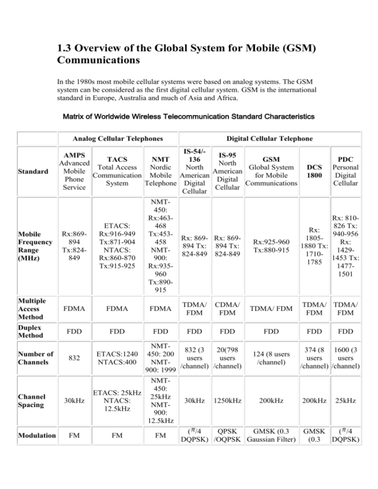
1.3 Overview of the Global System for Mobile (GSM) Communications In the 1980s most mobile cellular systems were based on analog systems. The GSM system can be considered as the first digital cellular system. GSM is the international standard in Europe, Australia and much of Asia and Africa. Matrix of Worldwide Wireless Telecommunication Standard Characteristics Analog Cellular Telephones Standard Digital Cellular Telephone IS-54/AMPS IS-95 TACS NMT 136 GSM Advanced North Total Access Nordic North Global System Mobile American Communication Mobile American for Mobile Phone Digital System Telephone Digital Communications Service Cellular Cellular Mobile Frequency Range (MHz) Rx:869894 Tx:824849 ETACS: Rx:916-949 Tx:871-904 NTACS: Rx:860-870 Tx:915-925 NMT450: Rx:463468 Tx:453458 NMT900: Rx:935960 Tx:890915 Multiple Access Method FDMA FDMA FDMA TDMA/ FDM Duplex Method FDD FDD FDD FDD Number of Channels Channel Spacing Modulation 832 30kHz FM Rx:925-960 Tx:880-915 Rx: 810826 Tx: Rx: 940-956 1805Rx: 1880 Tx: 142917101453 Tx: 1785 14771501 CDMA/ FDM TDMA/ FDM TDMA/ TDMA/ FDM FDM FDD FDD Rx: 869- Rx: 869894 Tx: 894 Tx: 824-849 824-849 NMT832 (3 20(798 ETACS:1240 450: 200 users users NTACS:400 NMT/channel) /channel) 900: 1999 NMT450: ETACS: 25kHz 25kHz NTACS: NMT12.5kHz 900: 12.5kHz FM FM 30kHz DCS 1800 PDC Personal Digital Cellular 1250kHz 124 (8 users /channel) 200kHz ( /4 QPSK GMSK (0.3 DQPSK) /OQPSK Gaussian Filter) FDD FDD 374 (8 1600 (3 users users /channel) /channel) 200kHz 25kHz GMSK ( /4 (0.3 DQPSK) Gaussian Filter) Channel Bit Rate 1.2288 270.833 kb/s Mb/s Reference: Philips Semiconductors (Innovation in Wireless Communication) n/a 1.3.1 History n/a n/a 48.6 kb/s 270.833 kb/s 42 kb/s 1.3.2 Architecture of the GSM network The GSM network can be divided into four main parts: The Mobile Station (MS). The Base Station Subsystem (BSS). The Network and Switching Subsystem (NSS). The Operation and Support Subsystem (OSS). The architecture of the GSM network is presented in figure 1. 1.3.2.1 Mobile Station A Mobile Station consists of two main elements: The mobile equipment or terminal. The Subscriber Identity Module (SIM). (a) The Terminal There are different types of terminals distinguished principally by their power and application: The `fixed' terminals are the ones installed in cars. Their maximum allowed output power is 20 W. The GSM portable terminals can also be installed in vehicles. Their maximum allowed output power is 8W. The handhels terminals have experienced the biggest success thanks to thei weight and volume, which are continuously decreasing. These terminals can emit up to 2 W. The evolution of technologies allows to decrease the maximum allowed power to 0.8 W. (b) The SIM The SIM is a smart card that identifies the terminal. By inserting the SIM card into the terminal, the user can have access to all the subscribed services. Without the SIM card, the terminal is not operational. The SIM card is protected by a four-digit Personal Identification Number (PIN). In order to identify the subscriber to the system, the SIM card contains some parameters of the user such as its International Mobile Subscriber Identity (IMSI). Another advantage of the SIM card is the mobility of the users. In fact, the only element that personalizes a terminal is the SIM card. Therefore, the user can have access to its subscribed services in any terminal using its SIM card. 1.3.2.2 The Base Station Subsystem The BSS connects the Mobile Station and the NSS. It is in charge of the transmission and reception. The BSS can be divided into two parts: The Base Transceiver Station (BTS) or Base Station. The Base Station Controller (BSC). (a) The Base Transceiver Station The BTS corresponds to the transceivers and antennas used in each cell of the network. A BTS is usually placed in the center of a cell. Its transmitting power defines the size of a cell. Each BTS has between one and sixteen transceivers depending on the density of users in the cell. (b)The Base Station Controller The BSC controls a group of BTS and manages their radio ressources. A BSC is principally in charge of handovers, frequency hopping, exchange functions and control of the radio frequency power levels of the BTSs. 1.3.2.3 The Network and Switching Subsystem Its main role is to manage the communications between the mobile users and other users, such as mobile users, ISDN users, fixed telephony users, etc. It also includes data bases needed in order to store information about the subscribers and to manage their mobility. The different components of the NSS are described below. (a) The Mobile services Switching Center (MSC) It is the central component of the NSS. The MSC performs the switching functions of the network. It also provides connection to other networks. (b) The Gateway Mobile services Switching Center (GMSC) A gateway is a node interconnecting two networks. The GMSC is the interface between the mobile cellular network and the PSTN. It is in charge of routing calls from the fixed network towards a GSM user. The GMSC is often implemented in the same machines as the MSC. (c) Home Location Register (HLR) The HLR is considered as a very important database that stores information of the suscribers belonging to the covering area of a MSC. It also stores the current location of these subscribers and the services to which they have access. The location of the subscriber corresponds to the SS7 address of the Visitor Location Register (VLR) associated to the terminal. (d) Visitor Location Register (VLR) The VLR contains information from a subscriber's HLR necessary in order to provide the subscribed services to visiting users. When a subscriber enters the covering area of a new MSC, the VLR associated to this MSC will request information about the new subscriber to its corresponding HLR. The VLR will then have enough information in order to assure the subscribed services without needing to ask the HLR each time a communication is established. The VLR is always implemented together with a MSC; so the area under control of the MSC is also the area under control of the VLR. (e) The Authentication Center (AuC) The AuC register is used for security purposes. It provides the parameters needed for authentication and encryption functions. These parameters help to verify the user's identity. (f) The Equipment Identity Register (EIR) The EIR is also used for security purposes. It is a register containing information about the mobile equipments. More particularly, it contains a list of all valid terminals. A terminal is identified by its International Mobile Equipment Identity (IMEI). The EIR allows then to forbid calls from stolen or unauthorized terminals (e.g, a terminal which does not respect the specifications concerning the output RF power). (g) The GSM Interworking Unit (GIWU) The GIWU corresponds to an interface to various networks for data communications. During these communications, the transmission of speech and data can be alternated. 1.3.2.4 The Operation and Support Subsystem (OSS) The OSS is connected to the different components of the NSS and to the BSC, in order to control and monitor the GSM system. It is also in charge of controlling the traffic load of the BSS. However, the increasing number of base stations, due to the development of cellular radio networks, has provoked that some of the maintenance tasks are transfered to the BTS. This transfer decreases considerably the costs of the maintenance of the system. 1.3.3 GSM Radio interface Frequency allocation Two frequency bands, of 25 Mhz each one, have been allocated for the GSM system: The band 890-915 Mhz has been allocated for the uplink direction (transmitting from the mobile station to the base station). The band 935-960 Mhz has been allocated for the downlink direction (transmitting from the base station to the mobile station). Multiple access scheme The multiple access scheme defines how different simultaneous communications, between different mobile stations situated in different cells, share the GSM radio spectrum. A mix of Frequency Division Multiple Access (FDMA) and Time Division Multiple Access (TDMA), combined with frequency hopping, has been adopted as the multiple access scheme for GSM. In GSM, a 25 Mhz frequency band is divided, using a FDMA scheme, into 124 carrier frequencies spaced one from each other by a 200 khz frequency band. Normally a 25 Mhz frequency band can provide 125 carrier frequencies but the first carrier frequency is used as a guard band between GSM and other services working on lower frequencies. Each carrier frequency is then divided in time using a TDMA scheme. This scheme splits the radio channel, with a width of 200 khz, into 8 bursts. A burst is the unit of time in a TDMA system, and it lasts approximately 0.577 ms. A TDMA frame is formed with 8 bursts and lasts, consequently, 4.615 ms. Each of the eight bursts, that form a TDMA frame, are then assigned to a single user. Channel structure A channel corresponds to the recurrence of one burst every frame. It is defined by its frequency and the position of its corresponding burst within a TDMA frame. In GSM there are two types of channels: The traffic channels used to transport speech and data information. The control channels used for network management messages and some channel maintenance tasks. The final choice for the GSM speech codec is a codec named RPE-LTP (Regular Pulse Excitation Long-Term Prediction). This codec uses the information from previous samples (this information does not change very quickly) in order to predict the current sample. The speech signal is divided into blocks of 20 ms. These blocks are then passed to the speech codec, which has a rate of 13 kbps, in order to obtain blocks of 260 bits. The final choice for the GSM speech codec is a codec named RPELTP (Regular Pulse Excitation Long-Term Prediction). This codec uses the information from previous samples (this information does not change very quickly) in order to predict the current sample. The speech signal is divided into blocks of 20 ms. These blocks are then passed to the speech codec, which has a rate of 13 kbps, in order to obtain blocks of 260 bits. GSM Phase 1 features Call Forwarding All Calls No Answer Engaged Unreachable Call Barring Outgoing - Bar certain outgoing calls(e.g. ISD) Incoming - Bar certain incoming calls (Useful if in another country) Global roaming - Visit any other country with GSM and a roaming agreement and use your phone and existing number* (see section on roaming) GSM Phase 2 features SMS - Short Message Service - Allows you to send text messages too and from phones Multi Party Calling - Talk to five other parties as well as yourself at the same time Call Holding - Place a call on Hold Call Waiting - Notifies you of another call whilst on a call Mobile Data Services - Allows handsets to communicate with computers Mobile Fax Service - Allows handsets to send, retrieve and receive faxes Calling Line Identity Service - This facility allows you to see the telephone number of the incoming caller on our handset before answering Advice of Charge - Allows you to keep track of call costs Cell Broadcast - Allows you to subscribe to local news channels Mobile Terminating Fax - Another number you are issued with that receives faxes that you can then download to the nearest fax machine. GSM Phase 2 + features Available by 1998 Upgrade and improvements to existing services Majority of the upgrade concerns data transmission, including bearer services and packet switched data at 64 kbit/s and above DECT access to GSM PMR/Public Access Mobile Radio (PAMR)-like capabilities GSM in the local loop Virtual Private Networks Packet Radio SIM enhancements Premium rate services (eg Stock prices sent to your phone) GSM 96 features In fact, there is no such thing as GSM 96. In MoU SERG there is a document called SE.03. In SE.03 you find the date for implementation of services. The date is 'coded' E in case this is essential at the start of operation of a GSM network. Services of that kind are: TS11 (basic speech), TS12 (emergency calls/112), SMS MT, Call forwarding/Call barring services and data/fax. Then there are E96 services, servrvices to be implemented for roamers before end 1996. The only service in this section is ODB Phase 2. (ODB=Operator Determined Barring). E97 is SMS MO (Short Message/Mobile Originated). The list for E98 is longer. One reason is to put presure on suppliers. Services included are CAMEL (to support PNP as a start), SOR, USSD, HSCSD and GPRS. 1.4 Third Generation Systems (3G) 1.4.1 Objectives and Requirements The ITU (International Telecommunication Union) , headquartered in Geneva, Switzerland is an international organization within which governments and the private sector coordinate global telecom networks and services. International Mobile Telecommunications-2000 (IMT-2000) is the ITU vision of global mobile access in the 21st century. Mobile communication has developed from first-generation analog to secondgeneration digital communications, and finally to the third-generation IMT2000. IMT-2000 will realize high-speed, wireless multimedia service providing wider roaming services globally. The key features of IMT-2000 are: a) high degree of commonality of design worldwide; b) compatibility of services within IMT-2000 and with the fixed network; c) high quality; d) small terminals for worldwide use; e) worldwide roaming capability; f) capability for multimedia applications and a wide range of services (e.g. video-teleconferencing, high speed Internet, speech and high rate data). IMT-2000 user bit rate versus coverage and mobility IMT-2000 enables users to transmit voice, data, and even moving images. In order to realize these services, IMT-2000 improves the data transmission speed up to 144Kbps in a high-speed moving environment, 384Kbps in a low-speed moving environment, and 2Mbps in a stationary environment. IMT-2000 provides services like Internet connection, transmission of large-scale data and moving contents photographed by digital cameras and videos, and software downloading. IMT-2000 will use 2GHZ, a worldwide common frequency band, allocated by the ITU. Unlike the size of bands per channel in Korea, which determine the data transmission speed (1.25MHz for digital mobile phones and PCS) IMT-2000 has selected 5MHz to provide multimedia services. Under the current system, maximum data transmission speed is 64Kbps, and toward late 2000, 384Kbps will be possible in IS-95C services. The size of IS-95C is included in IMT-2000 technology standards. At the early stage of IMT-2000 services, an 144Kbps-transmission speed of IS-2000 levels is expected. By around 2005 when IMT-2000 is in general use, a maximum speed of 2Mbps will be possible. 1.4.2 IMT-2000 HARMONIZATION IMT-2000 STANDARDS DEVELOPMENT INVOLVES EXTENSIVE GLOBAL OLLABORATION BETWEEN MANY DIFFERENT ORGANIZATIONS. IMT-2000 is a result of the collaboration of many entities, inside the ITU (ITUR and ITU-T), and outside the ITU (3GPP, 3GPP2, etc.) 10 TERRESTRIAL RADIO TECHNOLOGY PROPOSALS, PLUS 6 SATELLITE ONES, WERE RECEIVED IN JUNE 1998. Radio Transmission Technology (RTT) Proposals Proposal Description Environment Indoor Pedestrian Vehicular DECT Digital Enhanced Cordless Telecommunications UWC-136R6a Universal Wireless UWC-136- Communications R6b WIMS WCDMA Wireless Multimedia and Messaging DECT Source Satellite ETSI Project (EP) DECT UWC-136 USA TIA TR45.3 WIMS W-CDMA USA TIA TR46.1 Services Wideband CDMA TD-SCDMA China Academy of Telecommunication Technology (CATT) W-CDMA Japan ARIB W-CDMA II S. Korea TTA UMTS Terrestrial Radio Access UTRA (W-CDMA & TDCDMA) ETSI SMG2 NA: WCDMA North American: Wideband CDMA NA:W-CDMA USA T1P1-ATIS CDMA2000 Wideband CDMA (IS-95) CDMA 2000 USA TIA TR45.5 CDMA I Multiband synchronous DSCDMA W-CDMA I S. Korea TTA SAT-CDMA 49 LEO sats in 7 planes at 2000 km K:SATCDMA S. Korea TTA SW-CDMA Satellite wideband CDMA SW-CDMA ESA SWCTDMA Satellite wideband hybrid CDMA/TDMA SWCTDMA ESA ICO RTT 10 MEO sats in 2 planes at 10390 km ICO RTT ICO Global Communications Horizons Horizons satellite system HORIZONS Inmarsat TD-SCDMA Time-Division Synchronous CDMA W-CDMA Wideband CDMA CDMA II Asynchronous DSCDMA UTRA THE SLIDE SHOWS THE TERRESTRIAL PROPOSALS RECEIVED BY THE ITU AND THEIR PROGRESSIVE CONSOLIDATION INTO THE KEY CHARACTERISTIC RECOMMENDATION IN MARCH 1999. FURTHER HARMONIZATION IS ONGOING. IMT-2000 OFFERS SIGNIFICANT FLEXIBILITY WITHIN A SINGLE STANDARD. Note: The radio interfaces shown in the figure are commonly known by the following names: UTRA FDD (WCDMA) for IMT-DS; cdma2000 for IMT-MC; UTRA TDD, and TD-SCDMA for IMT-TC; UWC-136 for IMT-SC; and DECT for IMT-FT. FLEXIBILITY WITHIN THE IMT-2000 STANDARD MUST, HOWEVER, BE TRANSPARENT TO USERS, I.E. ONE MOBILE PHONE WORKS EVERYWHERE WITHOUT SIGNIFICANT PENALTIES IN SIZE, COST OR BATTERY LIFE. SOFTWARE-DEFINED RADIO TECHNOLOGIES CAN BE EXPECTED TO ALLOW PROGRESSIVELY INCREASING FLEXIBILITY WITHOUT INCURRING SIGNIFICANT PENALTIES IN HAND-HELD MOBILE UNITS.
