11.6.1: Skills Integration Challenge-Configuring and Testing the
Lab Network (Instructor Version)
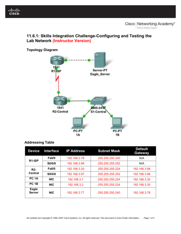
Topology Diagram
Addressing Table
Device
R1-ISP
Interface
IP Address
Subnet Mask
Default
Gateway
Fa0/0
192.168.3.78
255.255.255.240
N/A
S0/0/0
192.168.3.98
255.255.255.252
N/A
R2Central
Fa0/0
192.168.3.30
255.255.255.224
192.168.3.98
S0/0/0
192.168.3.97
255.255.255.252
192.168.3.98
PC 1A
NIC
192.168.3.1
255.255.255.224
192.168.3.30
PC 1B
NIC
192.168.3.2
255.255.255.224
192.168.3.30
Eagle
Server
NIC
192.168.3.77
255.255.255.240
192.168.3.78
All contents are Copyright © 1992–2007 Cisco Systems, Inc. All rights reserved. This document is Cisco Public Information.
Page 1 of 4
CCNA Exploration
Network Fundamentals:
Configuring and Testing Your Network
11.6.1: Skills Integration Challenge-Configuring and Testing the Lab Network
Learning Objectives
Build, test, and configure the entire lab network.
o Integrate skills from throughout the course.
Analzye the events involved in:
o Requesting a web page (DNS, ARP, HTTP, TCP, IP, Ethernet, HDLC).
o Tracing the route to the web server (DNS, UDP, ARP, ICMP, IP, Ethernet,
HDLC)
Background
Throughout the course, you have been developing network planning, building, configuring, and
testing skills. You have also developed conceptual understandings of networking protocols and
device algorithms. Here is an opportunity to test yourself: see if you can complete the entire
challenge (approximately 100 configurable components, though some are quite easy) in under 30
minutes.
Task 1: Plan.
Use the standard Exploration lab topology as you plan your IP addressing scheme:
Two 1841 routers with WIC-2T interface cards, installed in the right hand slot (one named
R1-ISP, which has the serial DCE WAN connection to R2-Central, and the Fa0/0 LAN
connection to Eagle_Server) and one named R2-Central (which has the serial DCE WAN
connection to R1-ISP and the Fa0/0 LAN connection to S1-Central)
One 2960TT Switch (S1-Central)
Two PCs named 1A and 1B
A server named Eagle_Server.
Note that both the Display names AND host names for all devices must be configured exactly,
and in general all strings (names, passwords, banners) should be typed exactly as specified in
these instructions, for the grading to work properly.
You have been given an IP address block of 192.168.3.0 /24. You must provide for existing
networks as well as future growth.
Subnet assignments are:
1st subnet, existing student LAN, up to 28 hosts (Fa0/0 on R2-Central, connected to
Fa0/24 on S1-Central)
2nd subnet, future student LAN, up to 28 hosts (not yet implemented)
3rd subnet, existing ISP LAN, up to 14 hosts (Fa0/0 on R1-ISP)
4th subnet, future ISP LAN, up to 7 hosts (not yet implemented)
5th subnet, existing WAN, point-to-point link (S0/0/0 on R1-ISP and S0/0/0 on R2Central)
All contents are Copyright © 1992–2007 Cisco Systems, Inc. All rights reserved. This document is Cisco Public Information.
Page 2 of 4
CCNA Exploration
Network Fundamentals:
Configuring and Testing Your Network
11.6.1: Skills Integration Challenge-Configuring and Testing the Lab Network
IP address assignments are:
For the server, configure the second highest usable IP address on the ISP LAN subnet.
For R1-ISP's Fa0/0 interface, configure the highest usable IP address on the ISP LAN
subnet.
For R1-ISP's S0/0/0 interface, configure the highest usable address on the existing WAN
subnet.
For R2-Central's S0/0/0 interface, use the lowest usable address on the existing WAN
subnet.
For R2-Central's Fa0/0 interface, use the highest usable address on the existing student
LAN subnet and connect it to the Fa0/24 interface on S1-Central.
For hosts 1A and 1B, use the first 2 IP addresses (two lowest usable addresses) on the
existing student LAN subnet and connect them to the Fa0/1 and Fa0/2 interfaces on S1Central.
For the switch management interface, use the second highest usable address on the
student subnet.
Task 2: Build and Configure the Network.
Build the network, taking care to make connections as specified. Configure both routers, the
switch, the server, and the two PCs.
Configure the routers using the CLI to practice your skills. The router configuration must include
"housekeeping" (display name, hostname, passwords, banner), interfaces (Fast Ethernet and
Serial), and routing (static route on R1-ISP, default route on R2-Central). The following login
passwords should all be set to "cisco" (no quotes): enable, console, and Telnet. The banners
should say **This is lab router R1-ISP. Authorized access only.** and **This is lab router R2Central. Authorized access only.**
The interfaces should be configured as specified in the IP addressing section above; use a clock
rate of 64000 on the R1-ISP S0/0/0 interface. The static route on R1-ISP should point to the
existing Student LAN subnet via R2-Central's serial interface IP address; the static route on R2Central should be a default static route which points via R1-ISP's serial interface IP address.
Whenever you configure a Cisco IOS device, be sure to save your configuration.
On the switch, configure the display name, hostname, banner (**This is lab switch S1-Central.
Authorized access only.**), login passwords for access (enable, console, and Telnet passwords
all set to "cisco"), and management interface (int vlan1). Whenever you configure a Cisco IOS
device, be sure to save your configuration.
For Hosts 1A and 1B, in addition to IP configuration, configure them to use DNS services. For the
server, enable DNS services, use the domain name eagle-server.example.com, and enable
HTTP services.
As you work, use "Check Results" to see what components still need to be configured. If you
want more practice, use "Reset Activity" and re-time yourself doing the entire configuration again.
All contents are Copyright © 1992–2007 Cisco Systems, Inc. All rights reserved. This document is Cisco Public Information.
Page 3 of 4
CCNA Exploration
Network Fundamentals:
Configuring and Testing Your Network
11.6.1: Skills Integration Challenge-Configuring and Testing the Lab Network
Task 3: Test and Analzye.
It is a good practice to test connectivity through ping and Telnet, and to examine routing tables.
Once you are convinced your network is working, make sure you have saved your configurations
on the Cisco IOS devices. Then power cycle the devices, and reset the network. In simulation
mode, request a web page while making the following protocols visible in the event list: DNS,
HTTP, Telnet, TCP, UDP, ICMP, ARP. Examine the packets as they are processed by the
devices to study protocol behavior, especially how IP is involved in everything. Also note the
algorithms used by hosts, switches, and routers. Explain the entire process to a peer. Power
cycle the devices to clear the network again, and, also in simulation mode, issue a traceroute to
the server from one of the PCs. Examine how trace is built up of ICMP echo requests. Again
explain the entire process to a peer.
Reflection
Relate the processes observed in Task 3 to the TCP/IP Protocol Graph. Your skills at modeling
networks in Packet Tracer will serve you well in subsequent courses.
All contents are Copyright © 1992–2007 Cisco Systems, Inc. All rights reserved. This document is Cisco Public Information.
Page 4 of 4

