Lab 11.5.6: Final Case Study - Datagram Analysis with Wireshark (Instructor
Version)
Learning Objectives
Upon completion of this exercise, students will be able to demonstrate:
How a TCP segment is constructed, and explain the segment fields.
How an IP packet is constructed, and explain the packet fields.
How an Ethernet II frame is constructed, and explain the frame fields.
Contents of an ARP REQUEST and ARP REPLY.
Background
This lab requires two captured packet files and Wireshark, a network protocol analyzer. Download the
following files from Eagle server, and install Wireshark on your computer if it is not already installed:
eagle1_web_client.pcap (discussed)
eagle1_web_server.pcap (reference only)
wireshark.exe
Scenario
This exercise details the sequence of datagrams that are created and sent across a network between a web
client, PC_Client, and web server, eagle1.example.com. Understanding the process involved in sequentially
placing packets on the network will enable the student to logically troubleshoot network failures when
connectivity breaks. For brevity and clarity, network packet noise has been omitted from the captures.
Before executing a network protocol analyzer on a network that belongs to someone else, be sure to get
permission- in writing.
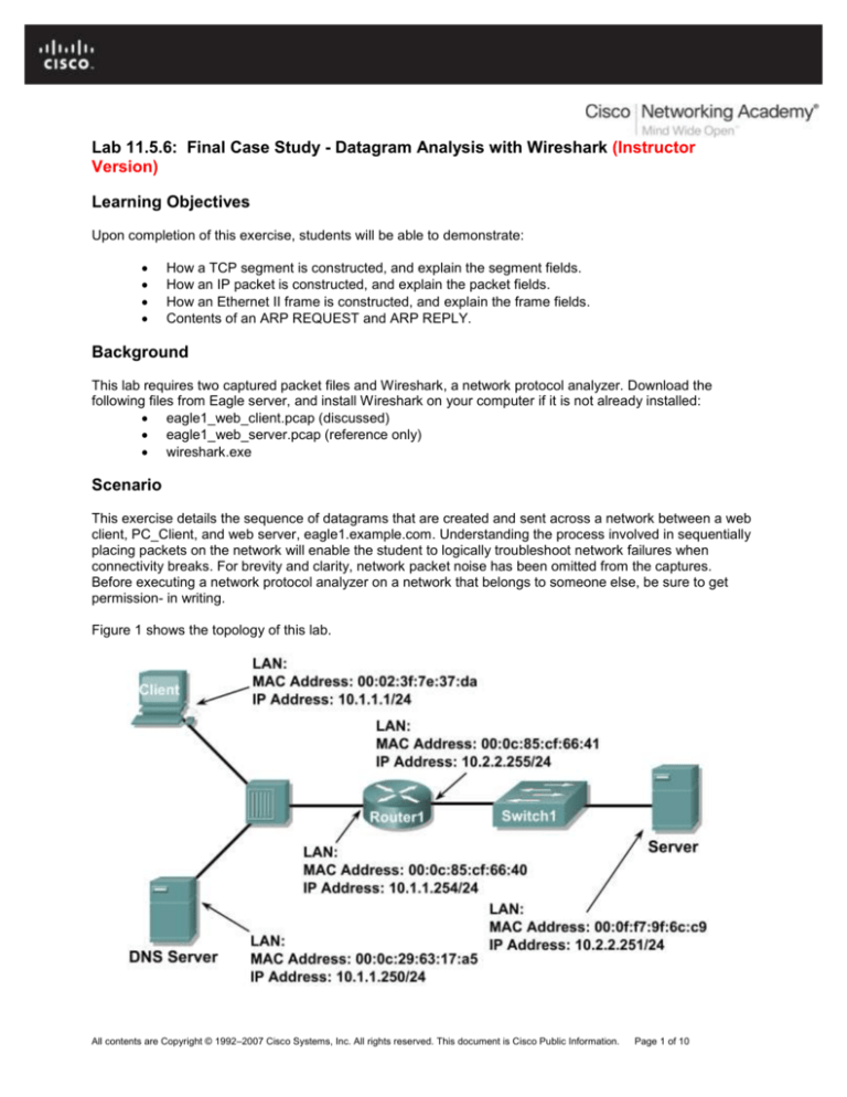
Figure 1 shows the topology of this lab.
All contents are Copyright © 1992–2007 Cisco Systems, Inc. All rights reserved. This document is Cisco Public Information.
Page 1 of 10
CCNA Exploration
Network Fundamentals: Planning and Cabling Networks
Lab 11.5.6: Final Case Study - Datagram Analysis with Wireshark
Figure 1. Network Topology.
Using Microsoft ® command line tools, IP configuration information and the contents of ARP cache are
displayed. Refer to Figure 2.
C: > ipconfig / all
Windows IP Configuration
Ethernet adapter Local Area Connection:
Connection-specific DNS Suffix . :
Description . . . . . . . . . . . : Intel(R) PRO/1000 MT
Network Connection
Physical Address. . . . . . . . . : 00:02:3f:7e:37:da
Dhcp Enabled. . . . . . . . . . . : No
IP Address. . . . . . . . . . . . : 10.1.1.1
Subnet Mask . . . . . . . . . . . : 255.255.255.0
Default Gateway . . . . . . . . . : 10.1.1.254
DNS Servers . . . . . . . . . . . : 10.1.1.250
C: > arp –a
No ARP Entries Found
C: >
Figure 2. PC Client initial network state.
A web client is started, and URL eagle1.example.com is entered, as shown in Figure 3. This begins
the communication process to the web server, and where the captured packets start.
Figure 3. PC Client with web browser.
Task 1: Prepare the Lab.
Step 1: Start Wireshark on your computer.
Refer to Figure 4 for changes to the default output. Uncheck Main toolbar, Filter toolbar, and
Packet Bytes. Verify that Packet List and Packet Details are checked. To insure there is no
automatic translation in MAC addresses, de-select Name Resolution for MAC layer and Transport
Layer.
All contents are Copyright © 1992–2007 Cisco Systems, Inc. All rights reserved. This document is Cisco Public Information.
Page 2 of 10
CCNA Exploration
Network Fundamentals: Planning and Cabling Networks
Lab 11.5.6: Final Case Study - Datagram Analysis with Wireshark
Figure 4. Wireshark default view changes.
Step 2: Load the web client capture, eagle1_web_client.pcap.
A screen similar to Figure 5 will be displayed. Various pull-down menus and sub-menus are available. There
are also two separate data windows. The top Wireshark window lists all captured packets. The bottom
window contains packet details. In the bottom window, each line that contains a check box, indicates that
additional information is available.
Figure 5. Wireshark with file eagle1_web_client.pcap loaded.
All contents are Copyright © 1992–2007 Cisco Systems, Inc. All rights reserved. This document is Cisco Public Information.
Page 3 of 10
CCNA Exploration
Network Fundamentals: Planning and Cabling Networks
Lab 11.5.6: Final Case Study - Datagram Analysis with Wireshark
Task 2: Review the Process of Data Flowing through the Network.
Step 1: Review Transport layer operation.
When PC_Client builds the datagram for a connection with eagle1.example.com, the datagram travels down
the various network Layers. At each Layer, important header information is added. Because this
communication is from a web client, the Transport Layer protocol will be TCP. Consider the TCP segment,
shown in Figure 6. PC_Client generates an internal TCP port address, in this conversation 1085, and knows
the well-known web server port address, 80. Likewise, a sequence number has been internally generated.
Data is included, provided by the Application Layer. Some information will not be known to PC_Client, so it
must be discovered using other network protocols.
There is no acknowledgement number. Before this segment can move to the Network Layer, the TCP threeway handshake must be performed.
TCP Segment
4
0
7
10
16
31
Source Port
Destination Port
Sequence Number
Acknowledgement Number
Data Offset
Reserved
ECN
Control Bits
Window
Checksum
Urgent Pointer
Options and Padding
Data
Figure 6. TCP Segment fields.
Step 2: Review Network layer operation.
At the Network Layer, the IPv4 (IP) PACKET has several fields ready with information. This is shown in
Figure 7. For example, the packet Version (IPv4) is known, as well as the source IP address.
The destination for this packet is eagle1.example.com. The corresponding IP Address must be discovered
through DNS (Domain Name Services). Until the upper layer datagram is received, fields related to the
upper layer protocols are empty.
IP Packet
4
0
Version
8
10
IHL
16
Total Length
Identification
TTL
31
TOS
Flags
Protocol
Fragment Offset
Header Checksum
Source IP Address
Destination IP Address
Data
Figure 7. IP Packet fields.
All contents are Copyright © 1992–2007 Cisco Systems, Inc. All rights reserved. This document is Cisco Public Information.
Page 4 of 10
CCNA Exploration
Network Fundamentals: Planning and Cabling Networks
Lab 11.5.6: Final Case Study - Datagram Analysis with Wireshark
Step 3: Review Data Link layer operation.
Before the datagram is placed on the physical medium, it must be encapsulated inside a frame. This is
shown in Figure 8. PC_Client has knowledge of the source MAC address, but must discover the destination
MAC address.
The destination MAC address must be discovered.
Ethernet II Frame Format
Preamble
Destination
Address
8 Octets
6 Octets
Source
Address
6 Octets
Frame
Type
2 Octets
Data
CRC
46-1500 Octets
4 Octets
Figure 8. Ethernet II frame fields.
Task 3: Analyze Captured Packets.
Step 1: Review the data flow sequence.
A review of missing information will be helpful in following the captured packet sequence:
a. The TCP segment cannot be constructed because the acknowledgement field is blank. A TCP 3way handshake with eagle1.example.com must first be completed.
b. The TCP 3-way handshake cannot occur because PC_Client does not know the IP address for
eagle1.example.com. This is resolved with a DNS request from PC_Client to the DNS the server.
c.
The DNS server cannot be queried because the MAC address for the DNS server is not known. The
ARP protocol is broadcast on the LAN to discover the MAC address for the DNS server.
d. The MAC address for eagle1.example.com is unknown. The ARP protocol is broadcast on the LAN
to learn the destination MAC address for eagle1.example.com.
Step 2: Examine the ARP request.
Refer to Wireshark, Packet List window, No. 1. The captured frame is an ARP (Address Resolution Protocol)
Request. Contents of the Ethernet II frame can be viewed by clicking on the check box in the second line of
the Packet Details window. Contents of the ARP Request can be viewed by clicking on the ARP Request
line in the Packet Details window.
1. What is the source MAC address for the ARP Request? _____________________
Answer: ___00:02:31:7e:73:da___
2. What is the destination MAC address for the ARP Request? _____________________
Answer: ___ff:ff:ff:ff:ff:ff___
3. What is the unknown IP address in the ARP Request? ______________________
Answer: _10.1.1.250___
4. What is the Ethernet II Frame Type? _____________________
Answer: __0x0806 (ARP) _
All contents are Copyright © 1992–2007 Cisco Systems, Inc. All rights reserved. This document is Cisco Public Information.
Page 5 of 10
CCNA Exploration
Network Fundamentals: Planning and Cabling Networks
Lab 11.5.6: Final Case Study - Datagram Analysis with Wireshark
Step 3: Examine the ARP reply.
Refer to Wireshark, Packet List window, No. 2. The DNS server sent an ARP Reply.
1. What is the source MAC address for the ARP Reply? _____________________
Answer: ___00:0c:29:63:17:a5___
2. What is the destination MAC address for the ARP Request? _____________________
Answer: __00:02:31:7e:73:da
_
3. What is the Ethernet II Frame Type? _____________________
Answer: __0x0806 (ARP) _
4. What is the destination IP address in the ARP Reply? _____________________
Answer: __10.1.1.1
_
5. Based on the observation of the ARP protocol, what can be inferred about an ARP Request
destination address and an ARP Reply destination address?
_____________________________________________________________________
_____________________________________________________________________
_____________________________________________________________________
Answer: The destination address for an ARP Request is a broadcast address, while the destination
address for and ARP Reply is a unicast address.
6. Why did the DNS server not have to send an ARP Request for the PC_Client MAC address?
_____________________________________________________________
_____________________________________________________________________
Answer: When an ARP Request is received, the source MAC address of the request is stored in the
receiver’s ARP cache.
Step 4: Examine the DNS query.
Refer to Wireshark, Packet List window, No. 3. PC_Client sent a DNS query to the DNS server. Using the
Packet Details window, answer the following questions:
1. What is the Ethernet II Frame Type? _____________________
Answer: __0x0800 (IP)
_
2. What is the Transport Layer protocol, and what is the destination port number?
_____________________
Answer: ___UDP, Port 53___
Step 5: Examine the DNS query response.
Refer to Wireshark, Packet List window, No. 4. The DNS server sent a DNS query response to PC_Client.
Using the Packet Details window, answer the following questions:
1. What is the Ethernet II Frame Type? _____________________
Answer: __0x0800 (IP)
_
All contents are Copyright © 1992–2007 Cisco Systems, Inc. All rights reserved. This document is Cisco Public Information.
Page 6 of 10
CCNA Exploration
Network Fundamentals: Planning and Cabling Networks
Lab 11.5.6: Final Case Study - Datagram Analysis with Wireshark
2. What is the Transport Layer protocol, and what is the destination port number?
_____________________
Answer: ___UDP, Port 1043___
3. What is the IP address for eagle1.example.com? _____________________
Answer: ___10.2.2.251___
4. A colleague is a firewall administrator, and asked if you thought of any reason why all UDP packets
should not be blocked from entering the internal network. What is your response?
_____________________
_____________________________________________________________________
_____________________________________________________________________
_____________________________________________________________________
Answer: DNS uses UDP for providing name translation. If all UDP packets were dropped at the
firewall, employees could not translate names to IP addresses. A better approach would be to
employ a stateful packet filter and create rules that permit established and related traffic through the
firewall.
Step 6: Examine the ARP request.
Refer to Wireshark, Packet List window, No. 5 and No 6. PC_Client sent an ARP Request to IP address
10.1.1.254.
1. Is this IP address different than the IP address for eagle1.example.com? Explain?
____________________________________________________________________
____________________________________________________________________
Answer: _Yes. Since 10.2.2.251 is on a different network than 10.1.1.0/24, PC_Client must have the
ARP address to the Gateway. The ARP Reply was from the Gateway.
Step 7: Examine the TCP 3-way handshake.
Refer to Wireshark, Packet List window, No. 7, No. 8, and No. 9. These captures contain the TCP 3-way
handshake between PC_Client and eagle1.example.com. Initially, only the TCP SYN flag is set on the
datagram sent from PC_Client, sequence number 0. eagle1.example.com responds with the TCP ACK and
SYN flags set, along with an acknowledgement of 1 and sequence of 0. In the Packet List window, there is
an unexplained value, MSS=1460. MSS stands for Maximum Segment size. When a TCP segment is
transported over IPv4, MSS is computed to be the maximum size of an IPv4 datagram minus 40 bytes. This
value is sent during connection startup. This is also when TCP sliding windows are negotiated.
1. If the initial TCP sequence value from PC_Client is 0, why did eagle1.example respond with an
acknowledgement of 1?
____________________________________________________________________
____________________________________________________________________
Answer: _TCP employs expectational acknowledgements. This means that the TCP
acknowledgement number sent is for the expected sequence number of the next packet.
2. In eagle1.example.com, No. 8, What does the IP Flag value of 0x04 mean?
____________________________________________________________________
Answer: IP Flag values:
8 4 2 1
0 . . . Reserved- (not set)
. 1 . . Don’t Fragment (set)
. . 0 . More Fragments (not set)
All contents are Copyright © 1992–2007 Cisco Systems, Inc. All rights reserved. This document is Cisco Public Information.
Page 7 of 10
CCNA Exploration
Network Fundamentals: Planning and Cabling Networks
Lab 11.5.6: Final Case Study - Datagram Analysis with Wireshark
3. When PC_Client completes the TCP 3-way handshake, Wireshark Packet List No 9, what are the
TCP flag states returned to eagle1.example.com?
____________________________________________________________________
Answer: TCP Flag states:
1.
2.
3.
4.
5.
6.
7.
Bit Position
0 . . .
. 0 . .
. . 0 .
. . . 1
. . . .
. . . .
. . . .
.
.
.
.
0
.
.
.
.
.
.
.
0
.
.
.
.
.
.
.
0
Flag
Congestion Window Reduced
ECN-Echo
Urgent
ACK
PSH
SYN
FIN
Task 4: Complete the Final Analysis.
Step 1: Match the Wireshark output to the process.
It has taken a total of nine datagrams sent between PC_Client, DNS server, Gateway, and
eagle1.example.com before PC_Client has sufficient information to send the original web client request to
eagle1.example.com. This is shown in Wireshark Packet List No. 10, where PC_Client sent a web protocol
GET request.
1. Fill in the correct Wireshark Packet List number that satisfies each of the following missing entries:
a. The TCP segment cannot be constructed because the acknowledgement field is blank. A TCP
3-way handshake with eagle1.example.com must first be completed. ________
b. The TCP 3-way handshake cannot occur because PC_Client does not know the IP address for
eagle1.example.com. This is resolved with a DNS request from PC_Client to the DNS the
server. ________
c.
The DNS server cannot be queried because the MAC address for the DNS server is not known.
The ARP protocol is broadcast on the LAN to discover the MAC address for the DNS server.
________
d. The MAC address for the gateway to reach eagle1.example.com is unknown. The ARP protocol
is broadcast on the LAN to learn the destination MAC address for the gateway. ________
Answer:
a. The TCP segment cannot be constructed because the acknowledgement field is blank. A
TCP 3-way handshake with eagle1.example.com must first be completed. ___No. 9, the
TCP ACK response to eagle1.example.com.
b. The TCP 3-way handshake cannot occur because PC_Client does not know the IP address
for eagle1.example.com. This is resolved with a DNS request from PC_Client to the DNS
the server. __No. 4, the DNS query response .
c.
The DNS server cannot be queried because the MAC address for the DNS server is not
known. The ARP protocol is broadcast on the LAN to discover the MAC address for the
DNS server. No 2, the ARP response from the DNS server.
All contents are Copyright © 1992–2007 Cisco Systems, Inc. All rights reserved. This document is Cisco Public Information.
Page 8 of 10
CCNA Exploration
Network Fundamentals: Planning and Cabling Networks
Lab 11.5.6: Final Case Study - Datagram Analysis with Wireshark
d. The MAC address for the gateway to reach eagle1.example.com is unknown. The ARP
protocol is broadcast on the LAN to learn the destination MAC address for the gateway.
_No. 6, the ARP response from the Gateway.
2. Wireshark Packet List No. 11 is an acknowledgement from eagle1.example.com to the PC_Client
GET request, Wireshark Packet List No. 10.
3. Wireshark Packet List No. 12, 13 and 15 are TCP segments from eagle1.example.com. Wireshark
Packet List No. 14 and 16 are ACK datagrams from PC_Client.
4. To verify the ACK, highlight Wireshark Packet List No. 14. Next, scroll down to the bottom of the
detail list window, and expand the [SEQ/ACK analysis] frame. The ACK datagram for Wireshark
Packet List No. 14 is a response to which datagram from eagle1.example.com? _______________
Answer: No. 13
5. Wireshark Packet List No. 17 datagram is sent from PC_Client to eagle1.example.com. Review the
information inside the [SEQ/ACK analysis] frame. What is the purpose of this datagram?
Answer: This datagram is a TCP window update to expand the window size.
6. When PC_Client is finished, TCP ACK and FIN flags are sent, shown in Wireshark Packet List No.
18. eagle1.example.com responds with a TCP ACK, and the TCP session is closed.
Step 2: Use Wireshark TCP Stream.
Analyzing packet contents can be a daunting experience, time consuming and error prone. Wireshark
includes an option that constructs the TCP Stream in a separate window. To use this feature, first select a
TCP datagram from the Wireshark Packet List. Next, select Wireshark menu options Analyze | Follow TCP
Stream. A window similar to Figure 9 will be displayed.
Figure 9. Output of the TCP stream.
All contents are Copyright © 1992–2007 Cisco Systems, Inc. All rights reserved. This document is Cisco Public Information.
Page 9 of 10
CCNA Exploration
Network Fundamentals: Planning and Cabling Networks
Lab 11.5.6: Final Case Study - Datagram Analysis with Wireshark
Task 5: Conclusion
Using a network protocol analyzer can serve as an effective learning tool for understanding critical elements
of network communication. Once the network administrator is familiar with communication protocols, the
same protocol analyzer can become an effective troubleshooting tool when there is network failure. For
example, if a web browser could not connect to a web server there could be multiple causes. A protocol
analyzer will show unsuccessful ARP requests, unsuccessful DNS queries, and unacknowledged packets.
Task 6: Summary
In this exercise the student has learned how communication between a web client and web server
communicate. Behind-the-scene protocols such as DNS and ARP are used to fill in missing parts of IP
packets and Ethernet frames, respectively. Before TCP session can begin, the TCP 3-way handshake must
build a reliable path and supply both communicating ends with initial TCP header information. Finally, the
TCP session is destroyed in an orderly manner with the client issuing a TCP FIN flag.
All contents are Copyright © 1992–2007 Cisco Systems, Inc. All rights reserved. This document is Cisco Public Information.
Page 10 of 10

