Table of Contents
advertisement
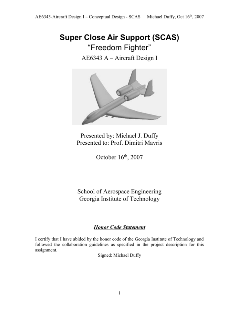
AE6343-Aircraft Design I – Conceptual Design - SCAS Michael Duffy, Oct 16th, 2007 Super Close Air Support (SCAS) “Freedom Fighter” AE6343 A – Aircraft Design I Presented by: Michael J. Duffy Presented to: Prof. Dimitri Mavris October 16th, 2007 School of Aerospace Engineering Georgia Institute of Technology Honor Code Statement I certify that I have abided by the honor code of the Georgia Institute of Technology and followed the collaboration guidelines as specified in the project description for this assignment. Signed: Michael Duffy i AE6343-Aircraft Design I – Conceptual Design - SCAS Michael Duffy, Oct 16th, 2007 Table of Contents Super Close Air Support (SCAS) ........................................................................................ i Table of Contents ................................................................................................................ ii List of Figures .................................................................................................................... iii List of Tables ..................................................................................................................... iv Executive Summary ............................................................................................................ 1 Fixed Wing Design (FWD) Tool Description: ................................................................... 3 Layout and Features ........................................................................................................ 3 Layout ......................................................................................................................... 3 Inputs........................................................................................................................... 4 Outputs ........................................................................................................................ 4 Methodology ................................................................................................................... 4 Mission Profile and Payload ....................................................................................... 5 Guessing an Initial Take-Off Gross Weight from Historical Data ............................. 6 Mission Analysis using Fuel Weight Fractions .......................................................... 7 Empty Weight Calculation ........................................................................................ 11 Allowable Empty Weight from Historical Data ....................................................... 11 Implementation of Design Tool for SCAS “Freedom Fighter”: ....................................... 12 Mission Analysis ........................................................................................................... 12 Constraint Analysis ....................................................................................................... 13 Limiting Constraints ................................................................................................. 13 Remaining Constraints .............................................................................................. 15 SCAS - “Freedom Fighter” Design Features: ................................................................... 15 Survivability.................................................................................................................. 16 Weapons ........................................................................................................................ 16 GPU-5/A 30-mm Gun Pod........................................................................................ 16 GBU-32 JDAM Missiles........................................................................................... 17 Aerodynamics ............................................................................................................... 18 Wing Planform .......................................................................................................... 18 Analysis Questions - Design Excursions .......................................................................... 18 Stand Off Weapon vs. Close Air Support ..................................................................... 18 Sustained Turn Rate Effect on Aircraft Structure ......................................................... 19 Field Length (NATO 8,002 ft vs. RFP required 2,000 ft) ............................................ 19 High Temperature (Afghanistan) Take-off and Landing .............................................. 20 Internal Stores Doubled (5,000 lbs vs. 10,000 lbs) ....................................................... 21 Fuel Consumption Reduction of 15% ........................................................................... 22 Add a Dash Segment to the Mission Analysis .............................................................. 23 Conclusion ........................................................................................................................ 23 Appendix A – SCAS “Freedom Fighter” Mission Summary ........................................... 24 Appendix B – Mattingly “Master Equation” Validation of FWD Tool............................ 25 References ......................................................................................................................... 26 ii AE6343-Aircraft Design I – Conceptual Design - SCAS Michael Duffy, Oct 16th, 2007 List of Figures Figure 1: A-10 Thunderbolt II 3-view ................................................................................ 2 Figure 2: SCAS “Freedom Fighter” 3-view Sketch Using VSP 1.2 ................................... 2 Figure 3: In the FWD Tool the ‘Mission Analyisis’ Tab is Laid Out in Order of the Seven Steps to Aircraft Sizing from Roskam ................................................................. 5 Figure 4: Super CAS Mission Profile to be Used for Mission Analysis ............................ 6 Figure 5: Historical Weight Trends for Fighter Aircaft ...................................................... 7 Figure 6: Historical Approach Speed from Roskam ......................................................... 14 Figure 7: Constraint Analysis Diagram for the SCAS “Freedom Fighter” ...................... 15 Figure 8: H-Tail is Choosen for “Freedom Fighter” to Improve Survivablity and Improved Aerodynamics .................................................................................... 16 Figure 9: GPU-5/A 30-mm Gun Placement Relative to Canopy (Behind Pilot View) .... 17 Figure 10: Four JDAM Missiles are Shown as the Most Limiting Case for Sizing and Constraints ......................................................................................................... 17 Figure 11: Comparison of Planform for the A-10 and SCAS “Freedom Fighter” Aircraft ............................................................................................................................ 18 Figure 12: Constraint Analysis of the SCAS “Freedom Fighter” for Increased Runway Length ................................................................................................................ 20 Figure 13: The Impact of Increased Temprature at Sea Level on Take-off and Landing Constraints ......................................................................................................... 21 Figure 14: Constraint Analysis for the SCAS “Freedom Fighter” with a 15% Fuel Flow Reduction ........................................................................................................... 23 Figure 15: FWD Tool Matches Validation Points ............................................................ 25 iii AE6343-Aircraft Design I – Conceptual Design - SCAS Michael Duffy, Oct 16th, 2007 List of Tables Table 1: Comparison Data for A-10 and SCAS Vehicle “Freedom Fighter” ..................... 1 Table 2: Payload/Crew for SCAS Mission ......................................................................... 6 Table 3: Typical Fuel Fractions for Various Aircraft Types .............................................. 8 Table 4: Typical Input Values for the Breguet Range Equation for Different Aircaft Types .................................................................................................................... 9 Table 5: Wetted Area Constants Based on Surface Roughness from Roskam ................... 9 Table 6: Constants used to find Minimum Drag for Various Aircraft ‘Types’ from Roskam .............................................................................................................. 10 Table 7: Fuel Fraction Summary for SCAS “Freedom Fighter” ...................................... 11 Table 8: Operational and Empty Weight for the SCAS “Freedom Fighter” .................... 11 Table 9: Empty Weight Trends Based on Take-off Weight for Various ‘Types’ of Aircraft .............................................................................................................. 12 Table 10: Final Empty Weight for the SCAS “Freedom Fighter” ................................... 12 Table 11: Matching Caluated Empty Weight with HItorically Gound Empty Weight for the SCAS “Freedom Fighter” ............................................................................ 12 Table 12: Comparison of Baseline Design with an Improved 15% Fuel Flow Design .... 22 Table 13: Baseline Mission Summary for the SCAS “Freedom Fighter” ........................ 24 Table 14: Validation Inputs from GATECH AE6343 ...................................................... 25 iv AE6343-Aircraft Design I – Conceptual Design - SCAS Michael Duffy, Oct 16th, 2007 Executive Summary This report will detail the conceptual design and sizing of a Close Air Support (CAS) vehicle to full fill AE 6343 Fall 2007 Project 1, based on 2006-2007 AIAA Graduate Design Competition RFP [1]. The primary goal of this vehicle is to replace the aging yet invaluable A-10 Thunderbolt II, with a faster, higher range capable aircraft. In addition to replacement of the A-10’s, the role of this new air vehicle will be to bridge the gap between the A-10 (CAS vehicle) and the F-16/F/18 (pure fighter vehicle), hence the name Super Close Air Support (SCAS). To facilitate the conceptual design and analysis of this aircraft a spreadsheet Fixed Wing Design (FWD) tool was created using an energy based approach for aircraft design. This method, outlined in AE 6343 class, Mattingly [4], and Roskam [6] is the basis of this report. The reader of this report, armed with the FWD tool, Mattingly, and Roskam, should be capable of repeating the conceptual design of this SCAS vehicle outlined in this report or any other fixed wing aircraft. The initially found design solution SCAS vehicle named “Freedom Fighter” is compared to the current A-10 Thunderbolt II in Table 1, and accompanying 3-views are shown in Figure 1, and Figure 2. TABLE 1: COMPARISON DATA FOR A-10 AND SCAS VEHICLE “FREEDOM FIGHTER” A-10 Thunder Bolt II SCAS “Freedom Fighter” TOGW Thrust T/W Thrust Loading Wing Span Length Wing Area W/S Wing Loading Ceiling Range Vmax 51,000 lbs 9,065 lbs x 2 0.28 57’6” 53’4” 547 sq.ft. 93 psf 45,000 ft 695 nm 365 knots 59,488 lbs 18,600 lbs x 2 0.625 69’ 58’7” 850 sq.ft. 70 psf 45,000 ft 1,600 nm 550 knots 1 AE6343-Aircraft Design I – Conceptual Design - SCAS Michael Duffy, Oct 16th, 2007 57’6” 53’4” FIGURE 1: A-10 THUNDERBOLT II 3-VIEW 69’ 58’7” FIGURE 2: SCAS “FREEDOM FIGHTER” 3-VIEW SKETCH USING VSP 1.2* *Note about SCAS “Freedom Fighter” drawings: All “Freedom Fighter” drawings were made using NASA’s Vehicle Sketch Pad 1.2. This tool is provided as a free open source code from NASA to industry and academia. 2 AE6343-Aircraft Design I – Conceptual Design - SCAS Michael Duffy, Oct 16th, 2007 Fixed Wing Design (FWD) Tool Description: The accompanying spreadsheet FWD tool, in which the basis of the report is written on, is meant to be a stand alone tool for any initial fixed wing design application. For this reason all references, tables, and figures used in sizing the SCAS vehicle are located in the FWD tool. Layout and Features Layout The FWD tool used for this project was created in Microsoft Excel. Key functions are split into different ‘tabbed’ worksheets and labeled by function. Tabs include: 1) Mission Profile – This tab is just a place holder for inserting the mission profile for reference. For the SCAS “Freedom Fighter”, the mission profile given by the RFP is shown in this tab 2) Mission Analysis – Based on user inputs, this tab is where the preliminary sizing of the aircraft’s take-off weight and empty weight are calculated. Figure 3 gives a screen shot of the mission analysis tab. After the initial inputs are entered, the user simply clicks the ‘Final Weight Empty’ button, and an Excel macro will vary take-off weight until empty weight calculated equals empty weight historical (or geometrically based). 3) Mission Summary – The mission summary collects all the input and output in one clear concise table, giving the user the ability to compare all segments of the mission. The SCAS “Freedom Fighter” baseline mission summary is located in Appendix A. 4) Constraint Analysis – Aircraft performance requirements are calculated in this tab using the Mattingly “Master Equation” [4]. Examples of performance requirements calculated for the SCAS “Freedom Fighter”: max speed, service ceiling, and take-off distance. 5) Thrust to Weight vs. Wing Loading – A summary graph shows the constraint analysis in the form of T/W (thrust loading) and W/S (wing loading) comparison. The user can then choose the lowest weight ‘feasible design’ and apply the wing loading and thrust loading to size the wing, and engine. 6) Drag Polar – The aerodynamic parameters of the wing are entered in the drag polar tab. The user can input a historically based drag polar here for conceptual design, and then for preliminary design resize with more sophisticated drag polar based on CFD or wind tunnel testing. This tab also contains historical regression data from Roskam [6] to aid in finding an initial drag polar for several classes of aircraft. 7) Fuel Fractions – Fuel fractions for various ‘types’ of aircraft are listed here from Roskam’s text. 8) Weight Empty Data – Historical data used for initial TOGW and WE for a variety of aircraft ‘types’ can be found in this tab. 9) Code Validation – This tab has validation points for the Mattingly “Master Equation” given in AE 6343 “Fixed Wing Design” course. 3 AE6343-Aircraft Design I – Conceptual Design - SCAS Michael Duffy, Oct 16th, 2007 Inputs All FWD tool inputs are labeled with references on where the current example SCAS variables can be found. Some of these reference tables and figures are shown in this report or in the appropriately labeled tabs in the FWD tool. Outputs Primary outputs from the FWD tool are shown on the bottom of the ‘mission analysis’ tab. The calculated empty weight is shown for the given mission requirements. The user pushes the ‘Find Empty Weight’ Button to calculate the empty weight. In addition to mission analysis, wing and engine sizing are done with constraint analysis found in the ‘constraint analysis’ tab. The user can input performance requirements, and plot thrust loading vs. wing loading. Methodology The FWD tool uses an energy balance approach of kinetic and potential energy to size aircraft, which is thoroughly described in Mattingly [4], Raymer [5], and Roskam [6]. This report will only review the basics of the method, and the remainder of the report will detail how the FWD tool was used to design the SCAS “Freedom Fighter” vehicle. Roskam outlines seven steps to sizing a vehicle. These steps are labeled in the FWD tool under the ‘mission analysis’ tab shown in figure 3: 1) Determine payload based on mission requirements. 2) Guess initial take-off weight from historical data trends. 3) Use fuel fractions to estimate weight of fuel burned during the mission. 4) Calculate operational weight empty. 5) Calculate weight empty. 6) Use historical trends to determine the weight empty for the initial take-off gross weight guess, figure 5 [6]. Note: That this step can be replaced by using actual weight estimates based on the geometry or individual weight trends for components. This will tend to give a more representative answer. 7) Change initial take-off weight guess and repeat steps 3 thru 6 until the weight empty calculated matches the weight empty from historical data 4 AE6343-Aircraft Design I – Conceptual Design - SCAS Michael Duffy, Oct 16th, 2007 Mission Analysis Step 1 Payload Calculations, W PL Ammunition Weight (1.62 lbs x 2000 rounds) Internal Stores Max External Stores Max W PL Total Crew Weight Crew (1x250lbs) Total 3,240 5,000 12,000 12,000 lbs lbs lbs lbs 250 lbs 250 lbs W CREW Step 2 Weight Take Off Guess Based on Historical Data, W TO_GUESS Aircraft Type W_PL W_TO V_MAX Range (lbs) (lbs) (kts) (nm) F.R. A10A 15,000 50,000 450 540 Grumman A6 17,000 60,400 689 1,700 Tornado F.Mk2 16,000 58,400 600 750 Average: 16,000 56,267 580 997 W TO_GUESS 59,488 lbs Step 3 Mission Fuel Weight Fractions, W F Profile Warm-up Taxi Step 4 Max Perforamnce Take-Off @ SL Weight Fractions: W 1/W TO 0.990 W 2/W 1 0.990 Max Power Climb to Opt. Alt. W 3/W 2 0.960 Cruise out 800 nm @ Optimum Speed/Alt W 4/W 3 0.930 Loiter for 20 min. @ 5,000ft W 5/W 4 0.986 20 min. Combat @ Corner Speed/SL W 6/W 5 0.974 Max Power Climb to Opt. Alt. W 7/W 6 0.960 Cruise Back 800 nm @ Optimum Speed/Alt W 8/W 7 0.927 Descend to SL @ Idle Thrust Setting W 9/W 8 1.000 20 min Loiter @ Endurance Speel/SL W 10/W 9 0.986 Landing with 30 min Reserve Fuel @ SL W 11/W 10 0.979 Total Fuel Fraction Total Weight of Fuel Required WL/WTO 16,516 lbs 0.722 WF Initial Operation Weight Empty, W OE W OE = W TO_GUESS - W F - W PL W OE Step 5 30,973 lbs Initial Weight Empty, W E W E = W OE - W TFO - W CREW W TFO WE - lbs 30,723 lbs Step 6 Allowable Weight Empty From Historical Data, W E_HIST A Regression Const. (Fighter + Ext Load) 0.5091 B Regression Const. (Fighter + Ext Load) 0.9505 Weight Empty from Historical Data W E_HIST 30,723 lbs Step 7 Adjust Take Off Weight Guess Until W E = WE_HIST First Iteration WE 30,723 lbs W E_HIST Error 30,723 lbs 0 lbs FIGURE 3: IN THE FWD TOOL THE ‘MISSION ANALYISIS’ TAB IS LAID OUT IN ORDER OF THE SEVEN STEPS TO AIRCRAFT SIZING FROM ROSKAM Mission Profile and Payload First a mission profile is defined by some set of requirements; in this case it is a close air support vehicle to replace aging A-10 anti-tank aircraft. Figure 4 from the RFP [1] shows the mission profile used in this design study. 5 AE6343-Aircraft Design I – Conceptual Design - SCAS Michael Duffy, Oct 16th, 2007 FIGURE 4: SUPER CAS MISSION PROFILE TO BE USED FOR MISSION ANALYSIS Payload is usually accompanied with a mission profile such as the one given for the SCAS mission. Payloads for this mission range from internal cargo of 5,000 lbs to external cargo of 12,000 lbs; therefore, the most limiting design constraint of 12,000 lbs is used. In addition to the weight of the payload the drag of the aircraft will also go up due to the additional excrescences. Table 2 outlines the internal cargo, external cargo and crew weight. TABLE 2: PAYLOAD/CREW FOR SCAS MISSION Payload Calculations, WPL Ammunition Weight (1.62 lbs x 2000 rounds) 3,240 Internal Stores Max 5,000 External Stores Max 12,000 W PL Total 12,000 Crew Weight Crew (1x250lbs) Total W CREW lbs lbs lbs lbs 250 lbs 250 lbs Guessing an Initial Take-Off Gross Weight from Historical Data To get an order of magnitude for what a new aircraft should look like and weigh, it is common to begin with historical data. First, a class of aircraft with similar mission requirements and/or capabilities is selected. For purpose of this study, the A-10, F-16, and F-18 all fall into the ‘Fighter’ class of aircraft. Figure 5 from Roskam [6] shows an historical regression of take off gross weight (TOGW) to weight empty (WE). This plot will later be used to correct the initial TOGW guess with the WE that is acquired from the mission analysis portion of the FWD tool. 6 AE6343-Aircraft Design I – Conceptual Design - SCAS Michael Duffy, Oct 16th, 2007 FIGURE 5: HISTORICAL WEIGHT TRENDS FOR FIGHTER AIRCAFT [6] For the purpose of sizing an initial take-off gross weight for the SCAS vehicle the A-10 with a payload of 15,000 lbs and a take-off gross weight of 50,000 lbs, the Grumman A6 (PL = 17,000lbs, TOGW = 60,400lbs) and the Tornado F.Mk2 (PL = 16,000 lbs, TOGW = 58,400lbs) are averaged to get and initial guess for the SCAS TOGW of 56,267 lbs. This weight will be used as a starting point for the mission analysis outlined in the next section. Mission Analysis using Fuel Weight Fractions The end goal for running mission analysis is simply to find the total fuel burned during the mission. To accomplish this, the mission is broken into small manageable segments, in which fuel fractions can be calculated or looked up. For short relatively simple 7 AE6343-Aircraft Design I – Conceptual Design - SCAS Michael Duffy, Oct 16th, 2007 segments such as taxi, take-off, climb, descent and landing, table 3, found in Roskam [6], can be used for a variety of aircraft. The SCAS “Freedom Fighter” is classified in the fighter airplane type in table 3. The fuel fractions used for “Freedom Fighter” are highlighted by the red box. These fuel fractions are multiplied together and then multiplied by the TOGW to determine the total fuel burned for the given mission. TABLE 3: TYPICAL FUEL FRACTIONS FOR VARIOUS AIRCRAFT TYPES [6] For cruise and loiter missions, the range and time need to be factored into the fuel fraction. To determine the fuel burned during a cruise and loiter, the Breguet Range equation is rearranged into the form shown in equation 1 and 2 from Roskam [6]. Values for cj and cp can be found from table 4. Table 4 can also be used to find typical values of L/D; however, if a drag polar is assumed the user can calculate L/D based on instantaneous mission weight. Equation (1) Equation (2) 8 AE6343-Aircraft Design I – Conceptual Design - SCAS Michael Duffy, Oct 16th, 2007 TABLE 4: TYPICAL INPUT VALUES FOR THE BREGUET RANGE EQUATION FOR DIFFERENT AIRCAFT TYPES [6] The drag polar is found using equations 3 thru 6, table 5, and 6 from Roskam [6], page 118 -120. , Equation (3) Equation (4) , , Equation (5) , Equation (6) TABLE 5: WETTED AREA CONSTANTS BASED ON SURFACE ROUGHNESS FROM ROSKAM [6] 9 AE6343-Aircraft Design I – Conceptual Design - SCAS Michael Duffy, Oct 16th, 2007 TABLE 6: CONSTANTS USED TO FIND MINIMUM DRAG FOR VARIOUS AIRCRAFT ‘TYPES’ FROM ROSKAM [6] Marked in red on tables 3 thru 6 are the values used for the SCAS “Freedom Fighter”; except, L/D was calculated at the beginning of each cruise and loiter segment, based on the instantaneous weight. In addition, the SCAS pays a drag penalty in cruise for the four external stores; this is accounted for in the min drag calculation. Roskam estimates 3.2 sq.ft. of drag for a typical external load, page 156. This increase in drag is captured in the L/D found in equations 1, and 2. Final fuel fractions for all mission segments are multiplied by TOGW to get the total fuel burned during the mission. Table 7 depicts the final fuel burn for the SCAS “Freedom Fighter”. Total Fuel burned during the mission is 16,516 lbs, including the 30 min reserve fuel. 10 Aircraft Type W_PL W_TO V_MAX Range Payload Calculations, W PL (lbs) (lbs) (kts) (nm) Ammunition Weight (1.62 lbs15,000 x 2000 rounds) 3,240 F.R. A10A 50,000 450 lbs 540 Internal Stores Max 5,000 Grumman A6 17,000 60,400 689 lbs 1,700 AE6343-Aircraft Design I –Stores Conceptual Design Oct External Max 12,000 lbs 750 Tornado F.Mk2 16,000 - SCAS 58,400 Michael 600 Duffy, Total 12,000 Average: 16,000 W PL 56,267 580 lbs 997 W TO_GUESS 59,488 lbs Crew FRACTION Weight TABLE 7: FUEL SUMMARY FOR SCAS “FREEDOM FIGHTER” Crew (1x250lbs) 250 lbs Mission Fuel Weight Fractions, W F Step 3 W CREW Total 250 lbs Step 1 Step 2 Step 3 Profile Weight Fractions: Weight Take W 1W /WTO_GUESS Warm-up TaxiOff Guess Based on Historical Data, 0.990 TO Aircraft Type W_PL W_TO V_MAX Range W Max Perforamnce Take-Off @ SL 0.990 2/W 1 (lbs) (lbs) (kts) (nm) W Max Power Climb to Opt. Alt. 0.960 3/W 2 F.R. A10A 15,000 50,000 450 540 W 4/W 3 Cruise out 800 nm @ Optimum Speed/Alt 0.930 Grumman A6 17,000 60,400 689 1,700 Loiter for 20 F.Mk2 min. @ 5,000ft 16,000 0.986 Tornado 58,400 W 5/W 4 600 750 Average: 16,000 56,267 W 6/W 5 580 997 20 min. Combat @ Corner Speed/SL 0.974 W TO_GUESS W 7/W59,488 lbs Max Power Climb to Opt. Alt. 0.960 6 Cruise Back 800 nm @ Optimum Speed/Alt Mission WF DescendFuel to SLWeight @ Idle Fractions, Thrust Setting 20 min Loiter @ Endurance Speel/SL Profile Landing with 30 min Reserve Fuel @ SL Warm-up Taxi Step 4 16th, 2007 Max TotalPerforamnce Fuel FractionTake-Off @ SL Max Power Climb to Opt. Alt. WF Total Weight of Fuel Required Cruise out 800 nm @ Optimum Speed/Alt Initialfor Operation Weight Loiter 20 min. @ 5,000ftEmpty, W OE Empty Weight Calculation 20 Combat @ -Corner Wmin. W F - WSpeed/SL OE = W TO_GUESS PL W 8/W 7 0.927 W 9/W 8 1.000 W 10/W 9 0.986 Weight Fractions: W 11/W 10 0.979 W 1/W TO 0.990 W 2/W 1 WL/WTO W 3/W 2 16,516 lbs W 4/W 3 0.990 0.722 0.960 W 5/W 4 0.986 W 6/W 5 0.974 0.930 W 7weight. /W 6 Max Power Climb to Opt. Alt. 0.9608 shows the Step 4 and 5 are simply calculating operational and empty Table W OE 30,973 lbs W /W Cruise Back 800 nm @ Optimum Speed/Alt 0.927 8 7 equations used and the values for the SCAS “Freedom Fighter”. The difference between W 9/W 8 Descend to SL @ Idle Thrust Setting Initial Weight Empty, operational and weight are theW Emission specific equipment that1.000 goes into the Step 5empty W 10/W 9 20 min Loiter @ Endurance Speel/SL 0.986 aircraft. For the SCAS W E“Freedom = W OE - W TFOFighter” - W CREW all mission equipment is assumed to be in the W 11/W 10 Landing with 30 min Reserve Fuel @ SL 0.979 weight empty. Final weight empty for the “Freedom Fighter” is- calculated to be 30,723 W TFO lbs lbs Total Fuel Fraction WL/WTO WE 30,723 lbs 0.722 WF Total Weight of Fuel Required 16,516 lbs TABLE 8:Step OPERATIONAL AND EMPTY FOR THE Allowable Weight EmptyWEIGHT From Historical Data, SCAS W E_HIST“FREEDOM FIGHTER” 6 Step 4 Initial Operation Weight Empty, W OE + Ext Load) A Regression Const. (Fighter B Regression Const. (Fighter + Ext Load) W OE = W TO_GUESS - W F - W PL Weight Empty from Historical Data W E_HIST W OE 0.5091 0.9505 30,723 lbs 30,973 lbs Step 7 Step 5 Adjust Take Off Weight Guess Until W E = WE_HIST Initial Weight Empty, W E First Iteration W WE = W - W -W 30,723 lbs E OE TFO CREW W E_HIST Error W TFO WE 30,723 0 30,723 lbs lbs lbs lbs Allowable Weight Empty From Historical Data, W E_HIST Const. (Fighter + Data Ext Load) 0.5091 Allowable EmptyAWeightRegression from Historical B Regression Const. (Fighter + Ext Load) 0.9505 The allowable empty Weight weight based historical can be found onelbsof W E_HIST Empty fromon Historical Data data 30,723 Step 6 three ways: 1) Table 9 from Roskam [6] shows the trends and constants used to calculate the Adjust Weightaircraft Guess Until W E =same WE_HIST‘type’. The red box in table 9 Step 7 weight empty basedTake on Off various of the First Iteration shows the values used for the SCAS “Freedom Fighter” WE 30,723 lbs 2) For a more representative weight that captures the individual weight break down W E_HIST 30,723 lbs for all major aircraft components, the user can choose to gather Error 0 lbs historical TOGW trends by component. Many of these trend equations can be found in Raymer [5], or Roskam [6] 3) For the most accurate method, the user can have a preliminary designer mock up each component, and have a weights engineer give estimates based on wetted 11 AE6343-Aircraft Design I – Conceptual Design - SCAS Michael Duffy, Oct 16th, 2007 area, structural thickness, and volumes, for each component. This however, is time consuming and manpower intensive; therefore, is usually saved for the preliminary design phase, as opposed to the conceptual design phase. TABLE 9: EMPTY WEIGHT TRENDS BASED ON TAKE-OFF WEIGHT FOR VARIOUS ‘TYPES’ OF AIRCRAFT [6] The initial take off gross weight guess is adjusted for several iterations before the empty weight shown in table 10 and 11 were found. Based on a TOGW of 59,488 lbs the “Freedom Fighter” weight empty is 30,723 lbs TABLE 10: FINAL EMPTY WEIGHT FOR THE SCAS “FREEDOM FIGHTER” Step 6 Allowable Weight Empty From Historical Data, W E_HIST A Regression Const. (Fighter + Ext Load) 0.5091 B Regression Const. (Fighter + Ext Load) 0.9505 Weight Empty from Historical Data W E_HIST 30,723 lbs TABLE 11: MATCHING CALUATED EMPTY WEIGHT WITH HITORICALLY FOUND EMPTY WEIGHT FOR THE SCAS “FREEDOM FIGHTER” Step 7 Adjust Take Off Weight Guess Until W E = WE_HIST First Iteration WE 30,723 lbs W E_HIST Error 30,723 lbs 0 lbs Implementation of Design Tool for SCAS “Freedom Fighter”: Mission Analysis Based in the mission analysis done in the previous section the take-off weight of 59,488 lbs was found to meet the mission profile requirements. Now the user must size the 12 AE6343-Aircraft Design I – Conceptual Design - SCAS Michael Duffy, Oct 16th, 2007 engine and wing to meet RFP’s point performance specifications. The next section will review how the constraint analysis was done for the SCAS “Freedom Fighter”. Constraint Analysis The ‘constraint analysis’ tab provides the user the ability to apply the Mattingly “Master Equation” [7] for thrust loading and wing loading to size the engine and wing. This ties together the mission analysis with the constraint analysis to give a final design. The user can specify the design constraints, and find the optimum (lowest weight) aircraft that meets all the specified requirements. Equation (7) The final design point for the SCAS “Freedom Fighter” is found at a minimum thrust loading of T/W =0.625 shown in figure 7. The constrains that drive the final design are take-off distance, landing distance, sustained turn, and climb rate. The remaining constraints have no impact on the design, but are still plotted to show compliance with the RFP requirements The SCAS “Freedom Fighter” T/W of 0.625 corresponds to a wing loading of 70 psf. Given the TOGW was found to be 59,488 lbs, the final wing area (850 sq.ft.) and thrust required (18,500 lbs x 2) can be computed. Limiting Constraints 1) 2,000 ft Take-off – Take-off distance is based finding a representative CLmax and applying it to the take-off distance equation found in Raymer [5]. CLmax for a fighter is found in Roskam [6] to be around 1.9. Rolling friction and flaps down drag are found in Roskam page 145. 2) 2,000 ft Landing Distance – Take-off distance is determined using the method found in Roskam, page 187. The approach speed is found from historical data from Roskam, figure 6. This is then applied to find the desired CLmax to fit the 2,000 ft field length for the SCAS. Since a CLmax used for take-off was 1.9, the same CLmax was used for landing. 13 AE6343-Aircraft Design I – Conceptual Design - SCAS Michael Duffy, Oct 16th, 2007 FIGURE 6: HISTORICAL APPROACH SPEED FROM ROSKAM [6] 3) 10,000 ft/min climb rate – Rate of climb is found using the Mattingly “Master Equation”, where the vertical velocity is defined as 10,000 ft/min. Be careful to correct the units to ft/s to match the units used in the “Master Equation”. 4) 12°/s Turn Rate – The load factor, n is determined using Raymer [5], page 106 where the user can input a turn rate and a free stream velocity. This equation is programmed into the FWD tool; hence, the user need only input turn rate and free stream velocity. The velocity is assumed to be the cruise speed of 459 knots, which makes the n value 5.14 g’s for the SCAS “Freedom Fighter”. The load factor is then plugged into the Mattingly “Master Equations” to determine the T/W vs. W/S. 14 AE6343-Aircraft Design I – Conceptual Design - SCAS 2,000 ft Landing Michael Duffy, Oct 16th, 2007 2,000 ft TakeTake-off 1.4 1.2 Feasible Design Space 12° 12°/s Sustained Turn @ 459 kts Final Design Point Combat Corner Speed of 275 kts T/W – Thrust Loading 1.0 0.8 10,000 ft Rate of Climb 0.6 Service Ceiling 45K ft 0.4 Level Cruise, 459 knots Max Speed, 550 knots 0.2 Stall Speed of 100 knots (SL, MTGW) 0.0 0 25 50 75 100 125 150 175 200 W/S – Wing Loading FIGURE 7: CONSTRAINT ANALYSIS DIAGRAM FOR THE SCAS “FREEDOM FIGHTER” Remaining Constraints 1) Combat Corner Speed at 275 knots – Similar to turn rate, corner speed is defined by a load factor, n. For the SCAS “Freedom Fighter” this value was found using Raymer [5], page 106 and setting the free stream velocity to 275 knots 2) Service Ceiling of 45,000 ft – Raymer defines that the service ceiling be the altitude at which the minimum rate of climb is 100 ft/min to allow for maneuver. 3) Max Speed, 550 knots – Max speed is defined in the RFP as 550 knots, and is assumed to be capable at the cruise altitude of 42,000 ft. The cruise altitude is defined by the example given in Roskam, page 118 for a ‘fighter’ aircraft. Because of the high mach number of 0.986, a component of minimum drag (CD_0 = 0.0025, found in Roskam, page 166) is added for compressibility. The wings are also swept aft according to Raymer [5] to reduce transonic drag (figure 11). 4) Min Stall Speed of 100 knots – Stall speed is defined in the RFP, and is required at sea level, max take-off weight. 5) Level Cruise Speed – Cruise speed of 459 knots is defined in Roskam [6], page 62, for a fighter. The altitude of 42,000 ft is also found in Roskam, page 62. SCAS - “Freedom Fighter” Design Features: It is up to the user of the FWD tool to do research on unique design constraints and features, such as engine placement, wing shape, gear configuration, etc. The tool only 15 AE6343-Aircraft Design I – Conceptual Design - SCAS Michael Duffy, Oct 16th, 2007 provides quantitative values for major design parameters. For this aspect of design Roskam [6] and Raymer [5] both have good initial layout and qualitative design discussions. For the SCAS vehicle several key design considerations come to mind. Survivability Raymer talks specifically about the A-10’s H-tail design as being a feature for survivability. More specifically the H-tail tail partially shields the engines from ground enemy fire, as does the mounting of the engines above the fuselage, and not under the wings. Figure 8 shows a quick design study using Vehicle Sketch Pad to model what the “Freedom Fighter” might look like with a conventional tail as opposed to an H-tail. For the “Freedom Fighter’s” design mission it is important to maintain high survivability, in addition the H-Tail provides a favorable end plate effect for the horizontal stabilizer; therefore, the H-tail is chosen over the conventional tail. More Horizontal Tail Required Because of No End Plate Effect H-Tail Partially Shields Engines from Enemy Ground Fire FIGURE 8: H-TAIL IS CHOOSEN FOR “FREEDOM FIGHTER” TO IMPROVE SURVIVABLITY AND IMPROVED AERODYNAMICS Weapons GPU-5/A 30-mm Gun Pod The RFP states that a GPU-5/A 30mm gun pod be fitted to the aircraft at all times. This presents a unique design layout problem, as forward firing guns can cause great distraction when smoke invades the pilots view (Raymer [5]). This can be over come by placing the muzzle behind the pilot, also making for a more favorable CG. Figure 9 shows cannon placement on the SCAS – “Freedom Fighter”. 16 AE6343-Aircraft Design I – Conceptual Design - SCAS Michael Duffy, Oct 16th, 2007 Forward Firing Cannon Located Aft of Pilot To Reduce Smoke Invasion on the Canopy FIGURE 9: GPU-5/A 30-MM GUN PLACEMENT RELATIVE TO CANOPY (BEHIND PILOT VIEW) GBU-32 JDAM Missiles The most limiting case in sizing the SCAS is the external stores of 12,000 lbs, Figure 10 shows their layout. FIGURE 10: FOUR JDAM MISSILES ARE SHOWN AS THE MOST LIMITING CASE FOR SIZING AND CONSTRAINTS 17 AE6343-Aircraft Design I – Conceptual Design - SCAS Michael Duffy, Oct 16th, 2007 Aerodynamics Wing Planform A swept wing was chosen for the “Freedom Fighter” to alleviate transonic drag rise (Figure 11). This is not a problem for the A-10; however, the “Freedom Fighter” will be flying at much higher speeds where drag divergence can severally penalize cruise. Compared to the A-10 which was designed to have all ‘flat wrapped’ surfaces (meaning no compound surfaces) the wing for the SCAS aircraft will be more expensive and harder to manufacture; however, with today’s use of composites, this is becoming less of an issue. Top View A-10 Thunderbolt II Wing Platform SCAS Peace Keeper Wing Platform Swept Aft to reduce transonic drag FIGURE 11: COMPARISON OF PLANFORM FOR THE A-10 AND SCAS “FREEDOM FIGHTER” AIRCRAFT Analysis Questions - Design Excursions Additional design excursions are provided to give the user examples of how changing the design constraints affect the sizing and performance of the SCAS “Freedom Fighter”. Stand Off Weapon vs. Close Air Support Design ‘excursion 1’ is found under the “mission excursion 1” tab in the FWD tool. The purpose of the first excursion is to see if the SCAS “Freedom Fighter” can perform a stand off mission as apposed to a close air support. The mission deviates from the 18 AE6343-Aircraft Design I – Conceptual Design - SCAS Michael Duffy, Oct 16th, 2007 baseline mission by replacing the 20 min loiter and combat segments with a one hour loiter and release of half the payload (bombs, strafe), The mission analysis is re-run and shows that the excursion 1 mission requires 16,279 lbs of fuel, this is less then the baseline design fuel capacity of 16,516; therefore, a surplus of 237 lbs fuel remains. This extra fuel could be used to extend the range, or loiter time. Sustained Turn Rate Effect on Aircraft Structure A sustained turn requires the aircraft structure to operate at higher loading factor then one. This means that a structure that is sized to just handle the weight of the aircraft at level flight, where n =1, would break if exposed to a sustained turn which requires the structure to hold 5-7 times the level flight loads. From a structural design prospective, a sustained turn exudes the largest loads that the aircraft will see in its flight envelope; therefore, is the critical design constraint. Field Length (NATO 8,002 ft vs. RFP required 2,000 ft) Increasing field length to any length over 2000 ft has no impact on the chosen T/W and W/S of the current final design point. Figure 12 shows that when the take-off and landing constraints are completely removed the minimum of thrust loading is still found at 70 psf. This means that only decreasing the field length to less than 2000 ft will impact the current design. Field length is not the only constraint a designer must consider when sizing for take-off and landing. Austere environments like Afghanistan, can affect take-off and landing ambient conditions like in the next section: the increased ambient temperatures can cause the landing and take-off performance to degrade, requiring a longer field for take-off. In addition, rough field can force the designer to size the gear stroke to allow for a minimum clearance between ground and obstacles. An example would be a minimum clearance required between the underside of the fuselage with the gear fully compressed and the ground (or rock, bump). 19 AE6343-Aircraft Design I – Conceptual Design - SCAS Michael Duffy, Oct 16th, 2007 1.4 Feasible Design Space w/o TakeTake-off and Landing Constraints 1.2 12° 12°/s Sustained Turn @ 459 kts T/W – Thrust Loading 1.0 Final Design Point Combat Corner Speed of 275 kts 0.8 10,000 ft Rate of Climb 0.6 Service Ceiling 45K ft 0.4 Level Cruise, 459 knots Max Speed, 550 knots 0.2 Stall Speed of 100 knots (SL, MTGW) 0.0 0 25 50 75 100 125 150 175 200 W/S – Wing Loading FIGURE 12: CONSTRAINT ANALYSIS OF THE SCAS “FREEDOM FIGHTER” FOR INCREASED RUNWAY LENGTH High Temperature (Afghanistan) Take-off and Landing The ambient condition plays a critical role in the take-off/landing constraint for the SCAS “Freedom Fighter”. Increasing the temperature at sea level from 59° to 110° to simulate an Afghanistan take-off mission caused the current baseline SCAS “Freedom Fighter” design to miss the 2,000 ft requirement. The run-way length would have to be 2,165 feet for the current SCAS “Freedom Fighter” design to take off at SL, 110° F. Figure 13 shows both take-off and landing for standard day 59° and the 110° “Afghanistan day”. The current design point lies outside of the new feasible design space with the adjusted requirement. 20 AE6343-Aircraft Design I – Conceptual Design - SCAS 2,000 ft Landing Michael Duffy, Oct 16th, 2007 2,000 ft TakeTake-off ,5 SL 0.8 10,000 ft Rate of Climb 0.6 0.4 SL, 59° T/W – Thrust Loading 1.0 12° 12°/s Sustained Turn @ 459 kts 9° SL , 11 1.2 0° SL, 110° 1.4 0.2 The hot day conditions forces the taketakeoff/landing lines above the current design point 0.0 0 25 50 75 100 125 150 175 200 W/S – Wing Loading FIGURE 13: THE IMPACT OF INCREASED TEMPRATURE AT SEA LEVEL ON TAKE-OFF AND LANDING CONSTRAINTS Internal Stores Doubled (5,000 lbs vs. 10,000 lbs) From a constraint analysis and mission performance perspective, increasing the internal stores will not impact the current design of the SCAS “Freedom Fighter”. Reason being is that the external stores is the most limiting case at 12,000 lbs, and increased minimum drag; however, internal stores can cause a large problem for volume limited configurations such as a ‘fighter’ type aircraft. Increasing internal stores can have a significant impact on structures and manufacturing. Increasing internal stores might interfere with the wing carry through structure. A wing box connects the load path between wings and fuselage. The wing box design is typically the lightest configuration; however, if the internal volume is occupied by internal stores, then the wing box might have to be replaced with less efficient carry through structure like ‘Ring Frames’ or ‘Beam Bending Frames’ as shown in Raymer [5], figure 8.12. In addition to structural considerations, manufacturing must be considered, as today many aircraft are assembled using subassemblies. Figure 8.23 in Raymer [5] shows the subassemblies for the SAAB Draken. Subassemblies can be affected by having large compartments that span the length of the fuselage, like for internal stores, causing the sub-assembly size to grow undesirably large. 21 AE6343-Aircraft Design I – Conceptual Design - SCAS Michael Duffy, Oct 16th, 2007 Fuel Consumption Reduction of 15% The 15% reduction in fuel flow significantly reduced the take-off gross weight of the baseline SCAS “Freedom Fighter” design. Table 12 shows comparison of the baseline with the improved fuel flow version. A reduction of mission fuel caused a cascade effect, reducing take-off weight by 12,000 lbs. The constraint analysis shown in figure 14 was not as significantly affected because the major driving constraints like climb rate, take-off and landing field length did no move; however, even with no change in thrust and wing loading, the reduced take-off weight reduces wing area, and required engine size, shown in table 12. TABLE 12: COMPARISON OF BASELINE DESIGN WITH AN IMPROVED 15% FUEL FLOW DESIGN Baseline SCAS SCAS “Freedom Fighter” “Freedom Fighter” w/ 15% Fuel Flow Reduction TOGW Thrust T/W Thrust Loading Wing Span Length Wing Area W/S Wing Loading Ceiling Range Vmax 59,488 lbs 18,600 lbs x 2 0.625 69’ 58’7” 850 sq.ft. 70 psf 45,000 ft 1,600 nm 550 knots 47,522 lbs 15,000 lbs x 2 0.625 55.2’ 47” 678 sq.ft. 70 psf 45,000 ft 1,600 nm 550 knots 22 AE6343-Aircraft Design I – Conceptual Design - SCAS 2,000 ft Landing Michael Duffy, Oct 16th, 2007 2,000 ft TakeTake-off 1.4 1.2 T/W – Thrust Loading 1.0 Final Design Point 0.8 12° 12°/s Sustained Turn @ 459 kts Combat Corner Speed of 275 kts 0.6 10,000 ft Rate of Climb Service Ceiling 45K ft 0.4 Level Cruise, 459 knots Max Speed, 550 knots 0.2 Stall Speed of 100 knots (SL, MTGW) 0.0 0 25 50 75 100 125 150 175 200 W/S – Wing Loading FIGURE 14: CONSTRAINT ANALYSIS FOR THE SCAS “FREEDOM FIGHTER” WITH A 15% FUEL FLOW REDUCTION Add a Dash Segment to the Mission Analysis Replace the 800 nm cruise with a 200 nm Mach 0.87 dash segment and the remaining 600 nm is a cruise at best range speed. The mission analysis for this profile can be found in the FWD tool under the ‘mission excursion 2’ tab. The take-off weight resized with the new segment and is found to increase from 59,488 lbs (baseline design) to 62,414 lbs. One driver of this increase is the added compressibility drag due to the high Mach number cruise. This drag penalty can be reduced with a more advanced wing planform. Sweeping the wing leading edge aft by some amount can reduce the compressibility drag rise. Figure 11 shown under the SCAS “Freedom Fighter” design features section shows a comparison of the A-10 planform which flies much slower then the SCAS “Freedom Fighter”. Conclusion The Fixed Wing Design Tool provided with this report has designed an aircraft with nearly twice the speed, and triple the range to meet the RFP [1] requirements. The SCAS “Freedom Fighter” design has been completely laid out step by step in this report for any user of the FWD tool to change and modify inputs to fit his or her design requirements. 23 AE6343-Aircraft Design I – Conceptual Design - SCAS Appendix A – Summary SCAS Michael Duffy, Oct 16th, 2007 “Freedom Fighter” Mission This appendix shows the last iteration of the SCAS “Freedom Fighter” from the mission analysis. TABLE 13: BASELINE MISSION SUMMARY FOR THE SCAS “FREEDOM FIGHTER” Mission Summary (Baseline Mission) Seg. 0 1 2 3 4 5 6 7 8 9 10 11 Description Warm-up Taxi Max Perforamnce Take-Off @ SL Max Power Climb to Opt. Alt. Cruise out 800 nm @ Optimum Speed/Alt Loiter for 20 min. @ 5,000ft 20 min. Combat @ Corner Speed/SL Max Power Climb to Opt. Alt. Cruise Back 800 nm @ Optimum Speed/Alt Descend to SL @ Idle Thrust Setting 20 min Loiter @ Endurance Speel/SL Landing with 30 min Reserve Fuel @ SL Altitude (ft) 0 0 0 42,000 42,000 5,000 0 42,000 42,000 0 0 0 Temp. (°F) 59.0 59.0 59.0 -90.6 -90.6 41.2 59.0 -90.6 -90.6 0.0 0.0 0.0 Density Velocity Range slug/ft^3 knots nm 2.377E-03 0.0 2.377E-03 0.0 2.377E-03 TBD 5.571E-04 350.0 25 5.571E-04 459.0 800 2.048E-03 226.6 800 2.377E-03 275.0 800 5.571E-04 350.0 825 5.571E-04 459.0 1,600 2.377E-03 459.0 1,600 2.377E-03 187.5 1,600 2.377E-03 0.0 1,600 24 q psf 0 0 0 167 150 256 167 167 119 0 CL CD L/D 0.0000 0.0000 TBD 0.3940 0.4088 1.1794 0.3379 0.3379 0.4400 0.0000 0.0172 0.0172 TBD 0.0282 0.0291 0.1160 0.0253 0.0253 0.0309 0.0172 0.00 0.00 13.97 14.07 10.17 13.36 13.36 14.23 0.00 W n-1/W n Fuel Burn (lbs) 1.000 0.990 595 0.990 1,184 0.960 3,516 0.930 7,434 0.986 8,161 0.974 9,477 0.960 11,477 0.927 14,985 1.000 14,985 0.986 15,600 0.979 16,516 Fuel (lbs) 595 589 2,332 3,918 727 1,315 2,000 3,508 615 916 Weight (lbs) 59,488 58,894 58,305 55,972 52,054 51,327 50,012 48,011 44,504 44,504 43,889 42,973 Beta 1.000 0.990 0.980 0.941 0.875 0.863 0.841 0.807 0.748 0.748 0.738 0.722 AE6343-Aircraft Design I – Conceptual Design - SCAS Michael Duffy, Oct 16th, 2007 Appendix B – Mattingly “Master Equation” Validation of FWD Tool Validation data was provided by AE6343 TA’s and is shown here for completeness. The blue line represents data calculated from the accompanying conceptual design tool. The red dots are the validation points. Only one set of data is shown for brevity, the remaining validation points are shown in the ‘Code Validation’ tab provided in the tool. 3.0 Validation Case 1: W/S and T/W 2.5 Calculated Using Mattingly Master Equation 2.0 T/W Provided Validation Points from GA TECH 1.5 1.0 0.5 W/S 0.0 0 50 100 150 FIGURE 15: FWD TOOL MATCHES VALIDATION POINTS TABLE 14: VALIDATION INPUTS FROM GATECH AE6343 Validation Point 1 α β n g R Velocity q CD0 K1 K2 dh/dt dV/dt 0.33 0.57 2.6 32.2 0.001832 695 442.4509 0.019 0.25 0.005 35 1.8 W/S ft/s2 slug/ft3 ft/s psf ft/s ft/s2 25 T/W 10 20 30 40 50 60 70 80 90 100 110 120 130 140 150 160 170 180 190 200 2.791 1.5549 1.168 0.9933 0.9035 0.8562 0.8332 0.8253 0.8275 0.8368 0.851247 0.869554 0.890831 0.91444 0.939915 0.966907 0.995147 1.024428 1.054586 1.085488 200 AE6343-Aircraft Design I – Conceptual Design - SCAS Michael Duffy, Oct 16th, 2007 References [1] Jimenez, H., Griendling, K., 2006-2007 AIAA Graduate Team Aircraft Design Competition – Modified RFP, Advanced Systems Design Lab, Georgia Institute of Technology, Atlanta, GA, 2007 [2] Jimenez, H., Griendling, K., AE6343 Aircraft Design Project #1 – 2007, Aircraft Constraint Analysis, Advanced Systems Design Lab, Georgia Institute of Technology, Atlanta, GA, 2007 [3] Jimenez, H., Griendling, K., An Energy Based Approach to Aircraft Design, Constraint Analysis – Part I, II, Advanced Systems Design Lab, Georgia Institute of Technology, Atlanta, GA, 2007 [4] Mattingly, J., Aircraft Engine Design, 2nd Edition, AIAA Education Series, 2002 [5] Raymer, D., Aircraft Design: A Conceptual Approach, 3rd Edition, AIAA Education Series, Reston, VA, 1999. [6] Roskam, J., Airplane Design: Part I, Preliminary Sizing of Airplanes, Roskam Aviation and Engineering Corporation, Ottawa, Kansas, 1985 26
