Final Report - Machine Intelligence Lab
advertisement
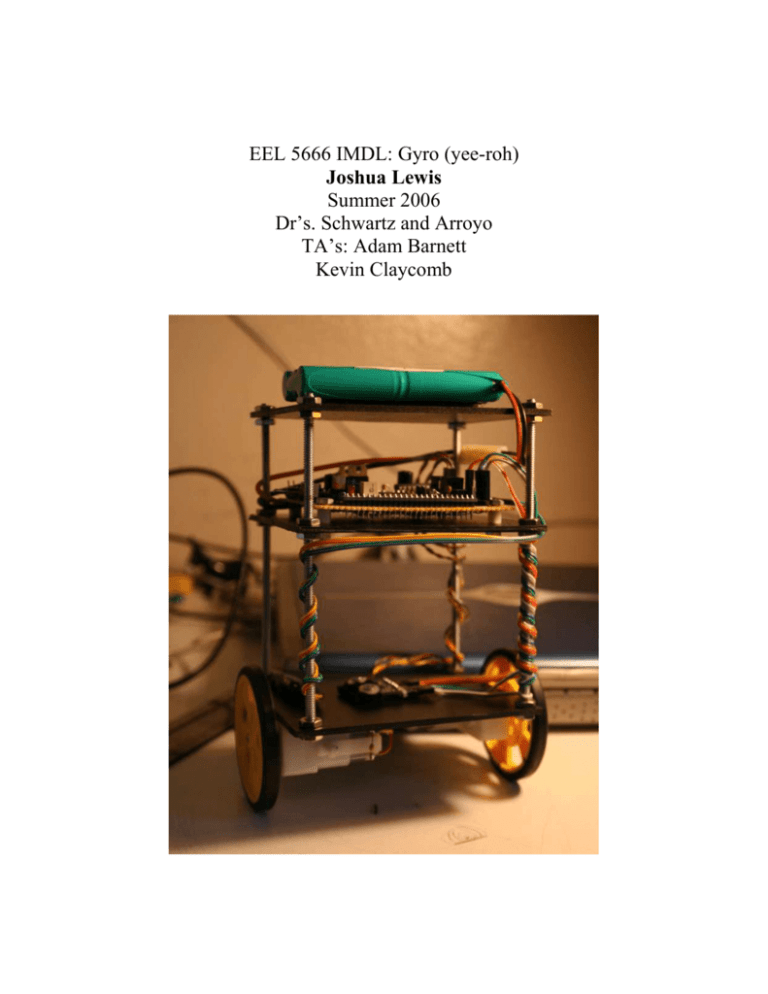
EEL 5666 IMDL: Gyro (yee-roh) Joshua Lewis Summer 2006 Dr’s. Schwartz and Arroyo TA’s: Adam Barnett Kevin Claycomb Page: 2/9 IMDL: Gyro Joshua Lewis 3/7/2016 Table of Contents Abstract………………………………………………………………………..3 Introduction…………………………………………………………………...3 Integrated System……………………………………………………………4 Mobile Platform………………………………………………………….……4 Actuation……………………………………………………………………….5 Sensors………………………………………………………………………...5 Behaviors……………………………………………………………………...8 Results……………………………………….…………………………………8 Conclusion…………………………………………………………………….9 Appendices…………………………………………………………..CD-Rom Page: 3/9 IMDL: Gyro Joshua Lewis 3/7/2016 Abstract Gyro (yee-roh) is a miniature self balancing robot based on the model of the inverted pendulum. He is designed to be small, efficient and highly intelligent. Gyro uses three different types of sensors to interact with the world around him. He fuses these three sensors together to drive a simplified PID control algorithm which allows Gyro to autonomously operate upright, with only two points of contact. Introduction Gyro is a solution to the inverted pendulum control problem. This classic engineering problem is much like trying to balance a broom on the tip of your finger, but Gyro must be able to complete this task while having freedom of mobility in only a single plane. This challenging robotics, electronics, and controls problem is the basis of my study for the Intelligent Machine Design Laboratory summer curriculum. To complete this task I have designed a small, robust, three tiered platform which will carry the sensors, microcontroller, and other peripherals necessary to allow Gyro to operate entirely autonomously. Gyro’s intelligence is written in C software and compiled for the Atmel ATMega128 microcontroller, which is interfaced with the sensors and motors. The main goal of the Gyro’s software system is to fuse the wheel encoder, gyroscope and accelerometer sensors to estimate the attitude of the platform and then to use this information to drive the wheels in the direction to maintain an upright and balanced position. Page: 4/9 IMDL: Gyro Joshua Lewis 3/7/2016 Integrated System Gyro incorporates all the necessary hardware and intelligence to act as a complete autonomous agent. Gyro uses a gyroscope and accelerometer to sense rotational velocity and angle of tilt. An Atmel ATMega128 microcontroller first fuses these sensors together with a Kalman filter which returns an angular position and angular velocity. A wheel encoder sends a pulsed signal to Gyro which allows him to sense his linear velocity. These three states are then fed into a P(Proportional)*D(differential) control algorithm which drives two geared electric motors to achieve vertical stability. Other peripherals interfaced with the ATMega are an LCD screen used for visual feedback and debugging and a BlueSmirf Bluetooth module which allows for remote programming of the gain coefficients in the control loop. The Bluetooth wireless communication is not used to actively control the robot but instead used to allow tweaking of the control loop during active run-time. This allows the user to achieve a stiff and accurate control algorithm in real time, without having to power-down and reprogram the ATMega microcontroller. The ATMega sends control signals to the Texas Instruments SN754410NE motor driver which allows for two channels of bidirectional pulse width modulated motor control. Power is served from an 11.1 V lithium-polymer battery, where it is regulated down to 5 and 3.3 volts respectively. Mobile Platform The first platform I designed was called MiniWay. He was made from a 1.5x5” sheet of perf-board and stood about six inches tall. All components were mounted directly to the chassis Page: 5/9 IMDL: Gyro Joshua Lewis 3/7/2016 and MiniWay used geared pager motors for mobility. This allowed for MiniWay to achieve an exceptionally compact design. Unfortunately this platform was extremely unstable and could not be controlled with my simple PD control algorithm. This led me to redesign a platform that is heavier, has a higher center of gravity, and is inherently more stable under passive and active conditions. Along came Gyro! (YEEE-ROH)!!! Gyro’s chassis is made from three tiers of Sintra, a PVC material. Four threaded rods hold these pieces together. The motors are mounted under the bottom tier. The inertial measurement unit or IMU is also mounted on the bottom tier along with Bluetooth module. Custom connectors spiral up the threaded rods to the middle tier where the microcontroller board is mounted. The lipo battery is Velcro’d to the top tier. The platform stands about 12 inches tall. Actuation All actuation is provided by two 143:1 gear motors with wheel and tire assembly. These hobby motors are not well suited for the task of balancing my platform. They lack the speed and accuracy needed for stiff control, but with little time left for experimenting with different motor options, these motors serve as the only actuation in Gyro’s platform. They are powered by the TI motor driver IC which runs directly off the 11.1 V power supply. Sensors Gyro uses a small array of sensors. In order to keep himself vertical, he needs to know which way is up. Humans and other mammals have a nifty little sensor in the inner ear which does this, and it's possible to do something similar mechanically. Page: 6/9 IMDL: Gyro Joshua Lewis 3/7/2016 A gyroscope, made from a spinning wheel, is the classical method for achieving a vertical reference. Unfortunately they are large and clumsy, which is not suitable for Gyro’s small design. Thanks to advances in micro-electro-mechanical systems (MEMS), the gyroscope has been reduced to an incredibly small package. Although hard to visualize, it turns out that if you have a vibrating tuning fork and rotate it, it will cause a measurable vibration in the perpendicular direction. By measuring this induced vibration you can tell which way it is rotating and how fast. This is known as a piezoelectric rate gyroscope and Gyro uses one to help achieve a vertical reference. Unfortunately, these gyroscopes are not perfect. They tend to report a small rate of rotation, even at rest. The gyroscope also develops a slow creeping tilt error due to integration. Since the sensor reports an angular velocity, the integrated value should result in a position. This is not a good estimate of position though because it is only relative to when the software actually started integrating. Gyro’s software will use the quick reacting rate gyroscope only for a short-term reading. Software will combine this measurement with that of an accelerometer to deduce a better estimate of absolute position. The accelerometer does give a physical reference because it is able to measure the static gravitational force which allows Gyro to make accurate measurements even at rest. Page: 7/9 IMDL: Gyro Joshua Lewis 3/7/2016 In my first attempt to combine the gyro and accelerometer I used this hand tuned feedback loop: This feedback loop worked well, but with no good way to correlate the estimated states with the actual, I was not able to determine the effectiveness of this loop. I also think that this loop was more susceptible to errors incurred by lateral acceleration. This was a problem because I was trying to assume that the accelerometer only reported the static acceleration due to gravity. This problem might have been rectified in software by measuring two axis of acceleration and using arctangent functions to resolve an estimated reference angle, but this was not pursued. Instead, I am using a Kalman filter written by Trammell Hudson of Rotomotion. This code is being actively developed in conjunction with autopilot.sf.net, an open-source collective interested in autonomous helicopter flight control systems. This Kalman filter acts as a one dimensional tilt sensor. The inputs to the filter are the single axis angular rate gyroscope and a zeroed single-axis accelerometer (positioned in the horizontal plane of motion). The two sensors are fused via the two state Kalman filter, with one state being the angle and the Page: 8/9 IMDL: Gyro Joshua Lewis 3/7/2016 other state the tracked gyro bias. Also, as byproduct of computing the angle, the filter also returns an unbiased angular velocity. The advanced set of sensors used for balance control are Analog Devices ADXL330 three axis accelerometer and the IDG-300 two axis gyroscope. Both these integrated chips run off of 3.3 volts and have been developed on a single board about the size of a quarter which weighs two grams. Behaviors The ability to maintain vertical balance is the fundamental action performed by Gyro. Balance is basically achieved by keeping the wheels under the center of gravity. When the robot tilts, it can maintain balance by driving the wheels in that direction. Inertial sensor readings and wheel encoders are the variables in a single PD equation which determines the speed and direction to drive the wheels. This PD loop is interrupt driven and updates at about 30Hz. Results Gyro has overcome many obstacles and revisions but has finally achieved vertical stability. He is currently awaiting a new controller board, as his last one was deep fried the night before the in-class demonstration day. The ATMega128 proved itself as a versatile and powerful microcontroller, perfectly suitable for this specific application. The IMU unit was prone to drift but was easy to implement and adequate for this small scale, low budget application. A more reliable and robust IMU would be needed for more serious applications needing to estimate attitude. Given more time, I would experiment with different drive train setups that would offer greater wheel speed and accuracy. Page: 9/9 IMDL: Gyro Joshua Lewis 3/7/2016 Conclusion Taking the Intelligent Machine Design Laboratory course this summer has been a fulfilling learning experience. Troubleshooting, debugging, and overcoming the many obstacles encountered during the design process has been the most challenging part of the course. Building Gyro was a difficult crash course in robotics. He incorporated many levels of design, from building the platform, interfacing the hardware, to the software and feedback control algorithm. Working individually and at my own pace has also been a learning experience. The summer has been filled with constant research and advice seeking. I thank my professors Dr. Schwartz and Dr. Arroyo; I thank the incredibly helpful and patient TA’s Adam and Kevin for there continued assistance throughout the course. I recommend building a balance robot to anyone looking to get their feet wet in electronics, robotics, inertial measurement units, and control systems. Appendices See Attached CD-ROM for source code, datasheets, pictures, and reference documents.
