How to build a human powered belt sander
advertisement
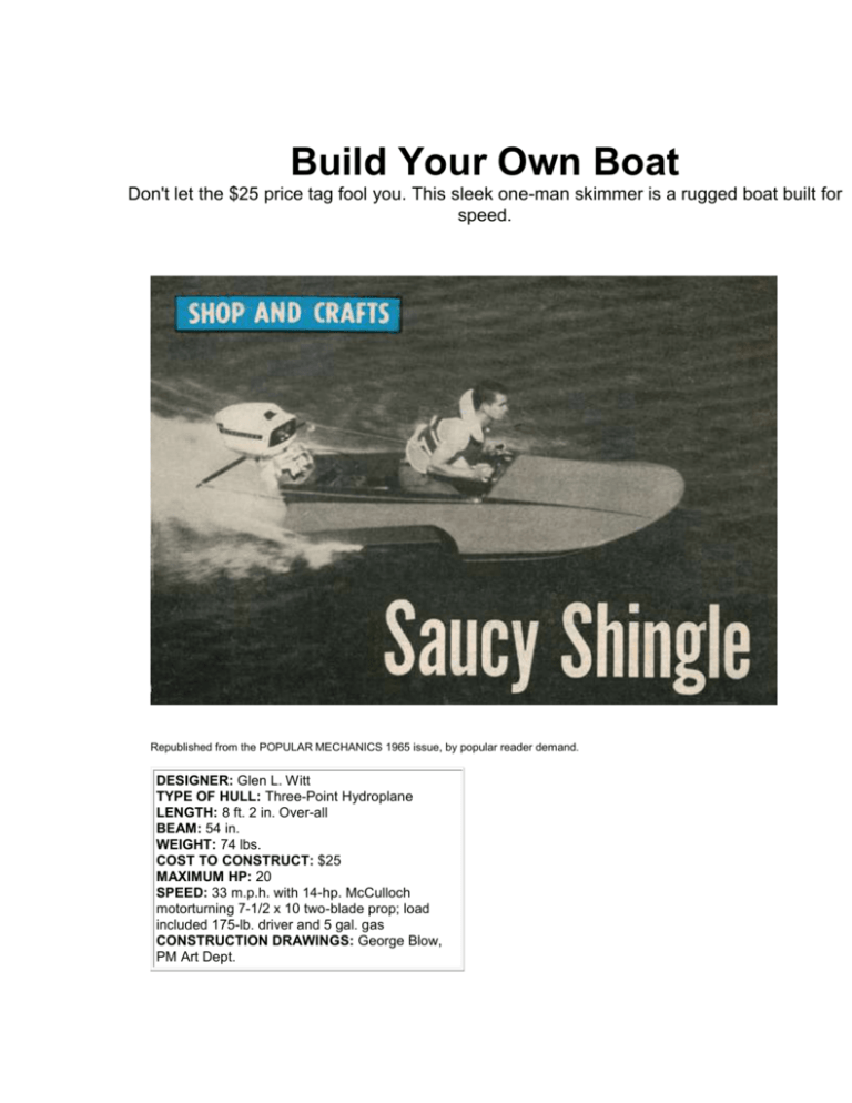
Build Your Own Boat Don't let the $25 price tag fool you. This sleek one-man skimmer is a rugged boat built for speed. Republished from the POPULAR MECHANICS 1965 issue, by popular reader demand. DESIGNER: Glen L. Witt TYPE OF HULL: Three-Point Hydroplane LENGTH: 8 ft. 2 in. Over-all BEAM: 54 in. WEIGHT: 74 lbs. COST TO CONSTRUCT: $25 MAXIMUM HP: 20 SPEED: 33 m.p.h. with 14-hp. McCulloch motorturning 7-1/2 x 10 two-blade prop; load included 175-lb. driver and 5 gal. gas CONSTRUCTION DRAWINGS: George Blow, PM Art Dept. WHILE NOT INTENDED for an assault on world speed records, Saucy Shingle is basically the same breed as those big record boats. Threepoint hydroplanes hold all major water speed records, and though her points may be smaller, she's a miniature thoroughbred. Small enough to fit inside a station wagon or on top of a compact car, the bare hull weighs only 74 lbs. It's an easy construction job that can be accomplished in a corner of your garage or basement. Study the drawings and photos carefully before starting to build. No building jig is required, but the steps must be carried out in order. Click above for high-resolution image. BILL OF MATERIALS Item Material No. Pcs. Bottom, Side & Runner DF PW 1 Planking Exterior AB Bow Lamination, Frame DF PW 1 Gussets & Floorboards Exterior AB Bow Piece No. 3, Dash DF PW 1 Beam No. 7, Transom Exterior AB and motor boards Decking and Cowling DF PW 1 Cover Exterior AB Bottom Battens Spruce or 3 Mahogany Anti-Trip Chine Spruce or 2 Mahogany Frames Spruce or 1 Mahogany Cross Pawl at Frames 1 Spruce or 2 &2 Mahogany Transom Cap Spruce or 1 Mahogany Sheer Clamp & Carlings Spruce or 4 Mahogany Deck Batten Spruce or 1 Mahogany Coaming Spruce or 1 Mahogany Size 1/4" x 4' x 8' 1/4" x 4' x 4' 1/2" x 4' x 4' 1/8" x 4' x 8' 1/2" x 2' x 6' 1/2" x 1-3/4" x 4' 6" 1/2" x 6' x 9' 3/4" x 1-1/4" x 4' 3/4" x 1-3/4" x 3' 3/4" x 3/4" x 8' 1/2" x 1" x 4' 1/2" x 7" (net) x 14' (makes two) GLUE: Resorcinol or Plastic Resin, Approx. 3 lbs. FASTENINGS: Nails: Ring-type boat nails, bronze or monel. 3/4" #14--1 lb., 1-1/4" #12--1/2 lb. Screws: Flathead wood type, hot dipped galvanized iron. 11/2" #8--22 only, 3" #14--3 only STEP 1. Cut the bottom planking sheet from 1/4-in. plywood, and mark the positions of the two frames, the transom and the battens. The runner chines are cut from 1/2-in. spruce and extend from Frame 1 forward on both of the outer edges of the bottom panel. Nail from the inside of the planking with 3/4-in. nails spaced 2 in. apart, after coating the contacting surfaces liberally with glue. STEP 2. The frames are cut from 1/2-in. spruce assembled over 1/4-in. plywood gussets. On Frame 1, notches for the non-trip chine and the bow piece are cut into the frame only; on the balance of the longitudinals and also on Frame 2, the notches are cut into both the framework and the plywood gussets. Coat contacting surfaces with glue and assemble the framework to the 1/4-in. plywood with 3/4-in. nails. After the two half assemblies are made, they are mounted over the 3/4 x 1-1/4-in. crossmember so that the inside distance that will contact the runner chines is accurately spaced at 16 in. on either side of the center line. STEP 3. Tack Frame 2 in place on the bottom planking, then permanently fasten it by driving nails through the underside into the cross member and through the runner chines into the side frame member. The three 1/2 x 2-in. bottom battens are nailed from the underneath side with 3/4-in. nails spaced about 3 in. apart. Note that at the aft end these members are bevelled to accommodate the 15deg. angle of the transom and aligned to the inside of the transom surface. STEP 4. The side planking is cut from 1/4-in. plywood and assembled to the chine and sheer clamp. Align the aft portion of the chine and sheer clamp carefully to allow for the thickness of the transom. The forward ends are allowed to run wild for cutting to length after assembly. Observe that the bottom edge of the plywood side planking and the chine are bevelled at a 30-deg. angle. During assembly, be sure that the bottom planking is straight as it contacts the chine member. Coat mating surfaces liberally with glue and nail with 3/4-in. nails spaced about 2 in. apart. Frame 1 is then assembled and slipped into position over the chine members. Notice that a notch will be made in the chine to enable the frame to be slipped into position over the chine. On the aft side of the Frame 1 gusset, a block is used to fasten the side planking to the frame. STEP 5. The sub-assembly just completed--side planking, chine and sheer with Frame 1--is now assembled to the RUNNER CHINE is installed on the bottom planking forward of the line marking position of Frame 1 TWO FRAMES are secured to different subassemblies which are then assembled to form the hull framing WHEN ASSEMBLED, note that the bevelled chine member extends forward to where it meets Frame 2 bottom planking. The chine should run forward to contact with Frame 2. The sheer clamp is left to run wild over the top of Frame 2. Work as rapidly as possible after coating the contact surfaces with glue, and nail through the bottom planking into the chine with 3/4-in. nails spaced about 2 in. apart. Where Frame 1 contacts the battens, drive a 1-1/4-in. nail into each. BOTTOM EDGE of the transom must be bevelled 15 deg. to mate with bottom planking when it's installed Click at left for high-resolution image of plans. STEP 6. The transom is cut from 1/2-in. plywood with the lower edge bevelled to contact the bottom planking. The inner motorboard is raised 1/2 in. above the bottom to act as a bearing surface for the bottom battens. The cap on the aft side of the transom must also be bevelled 15 deg. to accommodate the bottom planking. Assemble the side frame members to the transom, notching for the sheer clamp in the framework only and angling at the bottom for the chine members. Observe that the side frame member is left 1/2 in. above the bottom to provide a bearing for the chine members. Do not assemble the top frame member to the transom at this time. Cut it oversize on the carling end and set aside. The transom may now be assembled to the bottom planking. Nail through the bottom planking into the 3/4-in. member on the aft side with 1-1/4-in. nails spaced 2 in. apart. The side planking is nailed in position with 3/4-in. BLOCKING ON AFT side of Frame 1 should be secured to side planking before it's attached to frame nails. STEP 7. The 1/2-in. plywood bow piece is made in two halves. As indicated in the drawing, a 1/4-in. piece of plywood is laminated to the underside of the aft portion of each of these pieces. The bow piece is then assembled to the bottom planking fitting into the notches in Frames 1 and 2. After coating the contacting surfaces with glue, nail from the planking into the bow piece with 3/4-in. nails spaced about 2 in. apart. The excess bottom planking around the bow member is then trimmed off. NOTE: From this point until the boat is finished, the hull should be set on a level surface so that the transom is not twisted in relation to the runners. STEP 8. The sheer clamp is notched into Frame 2 and extended forward to the bow piece where it ends in a long taper. Spring any scrap member around the inner surface of the frames past the transom to simulate the coaming. Note that it will be necessary to bevel the side of the transom and motorboards to accommodate this member. After this bevel is cut, the top frame member of the transom may be installed allowing 1/2 in. clearance between the motorboards and coaming, and also providing the notch for the 3/4 x 3/4-in. carling. The carling, set vertically, is fitted into the notch in the bow piece first and then sprung aft into the notches in each of the frames. Leave the end overhanging at the transom for trimming later. Fasten with 1-1/4-in. nails into each of the frames and transom, after coating all of the contacting surfaces with glue. STEP 9. Fair or bevel all surfaces which will contact the side decking so that the planking will fit flush to the framework. This is a progressive process that may seem rather complicated, but a study of the drawings and photographs should help clear up the matter. After fairing, the 1/8-in. plywood sheet is clamped to the side deck area so that the outline can be marked roughly. If you're careful, it's possible to obtain all of the decking from a single 4 x 8ft. sheet. You won't have a great deal of excess material, however, so be careful in rough trimming. Next, the contact areas of the deck are coated liberally with glue and the side decking fastened around all the outer extremities with 3/4in. nails spaced about 2 in. apart. It isn't necessary to fasten to any of the inner contact points. The opposite side is put on and any excess trimmed. STEP 10. The coamings are cut from 1/2-in. mahogany and, preferably, rabbetted on the top edge to receive the decking. (If preferred, the decking may merely lap over the coaming with the routed groove being eliminated.) The coaming is fitted into the notch in the bow piece with the point extending over the top of this member. It is progressively sprung around the hull on the inside of the carling and frames and notched out on the aft end to fit over BOW PIECE made in two halves fits in notches in frames and rests on the bottom planking assembly WHEN ALL FRAMING has been installed, it must be faired to assure perfect mating with the planking BY CAREFUL CUTTING you can obtain all the decking from a single sheet of plywood, so don't rush it the transom and extend flush with the outer motorboard. In assembly, coat the contacting surfaces with glue and fasten with 1-1/4-in. nails spaced about 6 in. Click at left for high-resolution image of plans. STEP 11. The dash beam and the forward deck beam at Frame 2 are fastened against blocking provided on the coaming. The dash beam must be bevelled on the bottom to contact the 1/2 x 2-in. center bottom batten. At this point it rests against the frame and is canted forward as indicated in the drawings. In assembly, use two 1-1/2-in. No. 8 screws to fasten the dash beam at the contact point with Frame 1 and bottom batten. STEP 12. The hull is now turned upside down and the 1/2 x 1-3/4-in. non-trip chine installed. A long bevel is cut so that this member will rest on the bow piece. Corner glue blocks are installed at the junctions of Frames 1 and 2 with the runner chines. The bottom area is then faired for both the runner chine and the runner bottom. (This operation is similar to fairing the frame for the decking.) The 1/4-in. antitrip planking is fitted first. Cut it slightly oversize and do any necessary trimming after fastening it in place. After coating the area liberally with glue, begin fastening it along the bow piece. Then use a C-clamp to pull the non-trip chine so that the aft portion is parallel to the runner chine. This section must be fiat. After pulling the chine down with the C-clamp, fasten it along the member with the 3/4-in. nails spaced about 2 in. apart. The area is then faired flush at the nontrip chine and the runner bottom planking installed, lapping FAIR DECKING edge flush to the vertical carling so that the coaming will mate tightly for a good joint it over the non-trip planking. It, too, is bedded in glue and nailed with 3/4-in. nails spaced about 2 in. apart. STEP 13. Before finishing the forward decking, the interior should be painted with a dry-rot preventative. Cover as much of the area as possible, particularly down in the runners where water may tend to settle. The cowl plywood is fitted on one side of the coaming and tacked into position while the other side is fitted. The panel will tend to buckle as this is a slight compound curve, but as you progressively work the panel down the wrinkles will disappear. In fastening, again, use the 3/4-in. nails spaced about 2 in. STEP 14. The transom knee may be cut from any scrap 2in. material. The distance you mount this below the transom top edge should actually depend upon the motor used. The maximum is 5-1/2 in., but it's desirable to mount the knee as close to the top as the motor clamps will allow. Drive three 3-in. No. 14 screws through the rear of the transom into the knee and three 1/2-in. No. 8 screws through the coaming on either side. The cap strip at the dash covers the exposed edge of the forward decking. It should be cut from the scrap material from the coaming to extend 3/4 in. above the decking. Round the edges generously and nail in place. STEP 15. Due to the weight-sensitive nature of the threepoint hydroplane, it is usually not fiberglassed. If you desire to fiberglass it, however, use a light cloth. In the prototype, the bottom was primed with a plywood sealer and then given three coats of marine varnish. The top side on the original was painted a brilliant red-orange. After sealing with the plywood primer, flat paint was applied and sanded until the grain had disappeared. Two coats of a marine enamel went on. BLOCKING MOUNTED on the inside of the coaming is used to secure dash beam and forward deck beam TURNING HULL OVER, the fairing is completed for planking. Note glue blocks at frame-chine junctions STEP 16. The steering should be a tiller rope type with the drum exposed or forward of the dash. These are available with a standard 15-in. wheel or a small 10-in. wheel. The tiller cable should lead through transom-type pulley sheaves recessed into the coaming, extend aft to a pulley on the bar mounted to the motor and then back down to the coaming where it joins the transom. A spring at this point maintains tension on the steering system at all times. A throttle control of the dead-man type or automatic release is recommended with larger motors, though a standard lever control can be used. To prevent slipping in turns, an aluminum fin is installed inboard of the port runner. PLANKING for non-trip chine should be bevelled flush with runner so it can be lapped by bottom planking PAINT INTERIOR of the boat before mounting forward decking, using good rot-preventative coating CAR STRIP on dash covers exposed edge of forward decking and projects about 3/4 in. above the surface Saucy Shingle can handle almost any motor below 20 hp. You can get adequate speed for small fry with a motor under 10 hp, but the stock propeller should be replaced with one to match the boat. To achieve maximum performance it will also be necessary to adjust the height of the motor on the transom with "rev sticks"--1/4-in. pieces of wood slipped under the motor bracket one at a time. For high speeds it is recommended that the driver wear a life jacket and crash helmet. For the small fry it goes without saying that this equipment is a must at all times.
