Ray Optics
advertisement
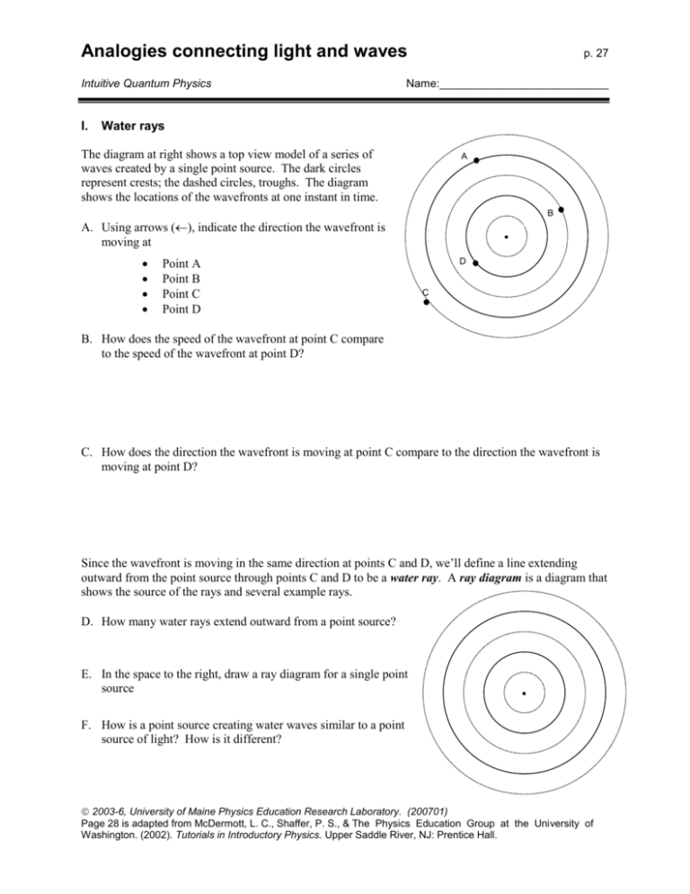
Analogies connecting light and waves Intuitive Quantum Physics I. p. 27 Name:___________________________ Water rays The diagram at right shows a top view model of a series of waves created by a single point source. The dark circles represent crests; the dashed circles, troughs. The diagram shows the locations of the wavefronts at one instant in time. A B A. Using arrows (), indicate the direction the wavefront is moving at Point A Point B Point C Point D • D C B. How does the speed of the wavefront at point C compare to the speed of the wavefront at point D? C. How does the direction the wavefront is moving at point C compare to the direction the wavefront is moving at point D? Since the wavefront is moving in the same direction at points C and D, we’ll define a line extending outward from the point source through points C and D to be a water ray. A ray diagram is a diagram that shows the source of the rays and several example rays. D. How many water rays extend outward from a point source? E. In the space to the right, draw a ray diagram for a single point source • F. How is a point source creating water waves similar to a point source of light? How is it different? 2003-6, University of Maine Physics Education Research Laboratory. (200701) Page 28 is adapted from McDermott, L. C., Shaffer, P. S., & The Physics Education Group at the University of Washington. (2002). Tutorials in Introductory Physics. Upper Saddle River, NJ: Prentice Hall. p.28 Analogies connecting light and waves II. Pictures of two source interference In last week's tutorial, we worked with diagrams of two point sources, as shown at right, and identified: lines of maximum constructive interference nodal lines In this part of the tutorial, we'll study what happens when the distance between the sources changes. This will teach us a few more things about wave interference (meaning when there is superposition of waves due to multiple sources). A. Obtain from the TA a transparency and matching paper with concentric circles on them. The circles represent wavefronts generated by each of two point sources. The transparency lets you change how far apart the two sources in the middle of the concentric circles are. 1. Suppose that the two sources are in phase and at the same location. Overlay the transparency on the paper to model this situation. 2. Explain why there are no nodal lines in this case. 3. Gradually increase the source separation, making note as nodal lines begin to appear. What happens to the number of nodal lines as the source separation increases? B. Imagine we have two sources, in phase, separated by some distance. How do the following change over time? (Assume the sources are kept in their original positions.) 1. Nodal lines 2. Lines of maximum constructive interference C. For the same sources as B, how does the water level at the following locations change over time? 1. A single point on a nodal line 2. A single point on a line of maximum constructive interference. Analogies connecting light and waves p.29 D. Ask your TA to set up the dipper the large wave tank with two dippers. Check your predictions. Did your observations agree with your predictions? If not, resolve any inconsistencies. III. Water waves incident on a single slit A. The diagram at right shows a shallow tray partially filled with water. Two small barriers are placed in the sides of the pan, and divide the pan into two regions. A dowel is placed in the end of Region I and gently rocked back and forth to create wavefronts. Region II Region I The three diagrams below show top-view diagrams of the tray. 1. On the first diagram below, sketch what you would expect to see in Region II if wavefronts moved faster in Region II than in Region I. How does the speed of the waves affect the distance between the waves? 2. On the second diagram below, sketch what you would expect to see in Region II if wavefronts moved slower in Region II than in Region I. Did you use the same reasoning as in question 1? 3. On the third diagram below, sketch what you would expect to see in Region II if wavefronts moved the same speed in Region II as in Region I. Diagram I: Faster in Region II Diagram II: Slower in Region II Diagram III: Same Speed in Region II By making these three different diagrams, you have predicted possible responses to describe what happens after the wave passes through the opening in the tank. The speed of the wave may or may not be affected by passing through the opening. p.30 Analogies connecting light and waves If the speed of the wave changes when it passes through the opening, the final speed may depend on the width of the opening as well. How could you check that? Discuss this with your group, then move on. B. Obtain a pan of water, dowel, and a set of ‘A’, ‘B’ and ‘C’ barriers. You can use the ‘A’ barriers to create a wide opening, the ‘B’ barriers to create a medium opening, and the ‘C’ barriers to create a narrow opening. Place a dowel in the water as shown in the previous diagrams. Gently rock the dowel back and forth to generate linear wavefronts at a constant rate. Observe what happens to the water waves for each set of barriers. 1. Which of the predictions from the diagrams on the previous page were observed? 2. Describe how the spacing of the wavefronts in Region II is affected, if at all, as the width of the opening is decreased. 3. Describe how the shape of the wavefronts in Region II is affected, if at all, as the width of the opening is decreased. C. It is often difficult to make periodic waves with the equipment at your table. Ask a staff member for photographs of periodic waves incident on openings of various widths. 1. Are the wavefronts in the photographs consistent with your observations above? 2. Identify the photograph(s) in which the slit does not significantly affect the shape of the wavefronts. 3. Identify the photograph(s) in which the slit acts most like a point source of water waves. How is it like a point source? Analogies connecting light and waves p.31 IV. Board Meeting #1 In addition to studying the wave nature of, well, waves by developing a model for the appearance of nodal lines and lines of maximum constructive interference, you have used the idea of water rays. Your instructor will assign you one of the questions below to address as a group. Take about five minutes to answer the question on your whiteboard, and then spend another five minutes thinking about the other question. Be prepared to participate in discussions of both questions. [Note that the comments in the square brackets are supposed to help you – and not the TA! – continue the discussion after whiteboard presentations are made.] 1. Using your ideas from Parts I and III, sketch ray diagrams for water waves passing through a wide opening and a narrow opening. [do the rays ever change direction? what can you say about a ray and the wavefront through which it passes? light rays make sense, but what is a water ray, anyway?] 2. Using your experience in this and previous tutorials, compare and contrast two dippers in water with two light bulbs. [is it reasonable to think that they are at all similar? what evidence do you have for them being different? what does your common sense say? when we refine our common sense about a thing, what do we learn?] Discuss the questions in class. Arrive at a consensus on each, take a break, and then move on to the next part of the tutorial. p.32 Analogies connecting light and waves V. Water waves incident on two slits. By now, you've seen that the shapes you see on the water after waves pass through an opening depend on the size of the opening. Some wave properties are most visible only in certain situations, such as in the case of waves passing through two very narrow openings. These openings are often referred to as slits. A. Use two ‘B’ barriers and one ‘A’ barrier to form a barrier in your pan of water that has two slits. Gently rock the dowel back and forth to generate linear wavefronts at a constant rate. 1. Describe the shape of the wavefronts in Region II. 2. Predict the shape of the wavefronts that would result in Region II if only one of the slits were open. Region II Barrier with two narrow slits Region I Dowel 3. Close one of the slits, and test your prediction. It is often difficult to see a clear pattern of wavefronts in Region II. Therefore, we will use diagrams and our knowledge of how waves interfere to build a model for wave behavior through two narrow slits. B. Obtain a top-view diagram of this situation from your TA. 1. Identify points on the diagram where The displacement of the water surface is zero The displacement of the water surface is the greatest above equilibrium The displacement of the water surface is the greatest below equilibrium Use different symbols or colors to mark the different locations. Look for patterns that will help you identify these points. 2. The gray box on the top-view diagram represents a solid barrier that is placed in the tank. Identify on the gray box locations of maximum constructive interference nodal lines This question should seem similar to you: it's the homework problem about the noise from two loudspeakers at a concert! The wave interference pattern isn't quite the same, but the phenomenon itself is the same. Analogies connecting light and waves p.33 C. The diagram below shows a perspective view of the same water tank. The equilibrium position of the water is shown (The equilibrium position of the water is when no waves are being created and the water is flat). Answer the following questions individually, then compare your sketches with your tablemates. 1. Periodic waves are created by rocking the dowel back and forth. Draw arrows on the gray barrier to describe what happens to the water level at various positions over time. You'll have to consider whether to draw the same arrows across the whole barrier. Equilibrium water level 2. Imagine a dye is placed in the water, and this dye leaves a mark on the gray barrier. Sketch the ink pattern that would be seen on the gray barrier after waves have been created for a period of time. (Think about what ink would do on a sheet of paper.) Equilibrium water level 3. Imagine that we replace the used gray barrier with a clean one, and move the slits closer together. What do you think will happen to the number of the nodes and maximum constructive interference points seen on the gray barrier? Sketch the ink pattern in addition to describing the change in words. Equilibrium water level 4. Third time's the charm! Imagine we replace the used barrier with a clean one (the third one), and completely close one slit. What do you think the pattern on the gray barrier will be? Sketch your answer below. Equilibrium water level p.34 Analogies connecting light and waves The activity on the previous page is one of the most important you will do in this tutorial. With it, we give you a visual marker, something to refer back to from now on. In lecture, you'll hear phrases like “It's just like with the gray barrier, because…” It’s so important, in fact, that we’re going to discuss it as a class in a board meeting. Board Meeting #2 As we just said, this gray barrier model is very important, and we want to take time to arrive at a classwide consensus on it. On your whiteboard, copy the four gray barrier sketches you made on the previous page. (If you haven’t come to a group consensus with your tablemates, now would be a good time to do so!) We’ll have a class discussion about the gray barrier model. After the class comes to a consensus, use the diagrams below (the questions are identical to the previous page) to record the ideas developed, especially if they differ from what you predicted on the previous page. 1. Arrows representing movement of the water at various positions over time: Equilibrium water level 2. Ink pattern formed on gray barrier by ink in water: Equilibrium water level 3. Ink pattern formed on gray barrier by ink in water when slits are moved closer together: Equilibrium water level 4. Ink pattern formed on gray barrier by ink in water when one of the slits is closed: Equilibrium water level Analogies connecting light and waves p.35 VI. Light through narrow slits We're going to move from water waves back to studying light. Rather than using bulbs, we'll use laser light. Also, we won't have masks with big holes but will use narrow slits instead. A. A laser is set up so that its beam of light is incident on a screen containing two narrow slits. The room is darkened. 1. Sketch what you would expect to see on the screen. 2. Explain why you sketched what you did. WARNING! Never look directly into a laser beam. Doing so can potentially cause permanent retinal damage or blindness. Always view from the sides. Viewing the light on a screen from a laser is not dangerous. Your TA will assist the class in the following experiments. B. The laser is placed so that it is at least 1 meter from the screen and turned on. 1. What do you observe? Sketch your observation below. 2. A slide with two narrow slits is placed between the laser and screen, a few centimeters from the laser. Sketch what you observe on the screen in the space below. C. Compare the pattern seen on the screen when light passes through two narrow slits to the pattern seen on the grey barrier when water waves pass through two narrow openings. 1. How, if at all, are the patterns similar? 2. How, if at all, are the patterns different? A portion of the pattern produced by a laser beam passing through two very narrow slits has been reproduced below: p.36 Analogies connecting light and waves A B 3. In questions 1 and 2 on the previous page, we made an analogy between water waves and laser beams passing through two slits. Using this analogy, predict (in words and with a sketch) what would happen in each of the scenarios below: a. The spacing between slits is decreased (the width of each slit remains unchanged). b. The spacing between slits is increased (the width of each slit remains unchanged). c. The screen is moved closer to the slide containing the slits. d. The laser is moved closer to the slide. 4. Ask a TA to perform the experiments. Did your observations agree with your predictions? If not, resolve any inconsistencies in the space above (be sure to think about your incorrect response before you change it – what did you learn as your answers change?). D. Suppose one of the slits were covered. Would the brightness of the screen increase, decrease, or stay the same at each of the following points? In each case, how do you know? 1. Point A 2. Point B Analogies connecting light and waves p.37 VII. Board Meeting #3 Your instructor will assign you one of the questions below to address as a group. 1. How, if at all, is it appropriate to say that light bends? [For discussion purposes, give examples, consider counter-examples, and be sure that you understand the representation being used with light rays and wavefronts and how they relate.] 2. The title of this tutorial already delivers the message that we want you to make an analogy between two things. How are your results consistent with your description of water waves in Section V.C? How are they inconsistent? [For discussion purposes, describe how the analogy works, how it doesn’t, and more importantly, how you define consistency between the two.] VIII. Computer simulations Once you have completed your board meeting, return to your desks and observe two web pages: A. Two source interference http://id.mind.net/~zona/mstm/physics/waves/interference/twoSource/TwoSourceInterference1.html This page shows two sources interfering, lets you determine if the waves are in sync or out of sync with each other, and lets you determine the wavelength. What is being shown? Crests or troughs? Can you find the lines of maximum constructive interference? The nodal lines? B. Two slit interference http://vsg.quasihome.com/interfer.htm This web page shows a single source passing through a double slit and arriving on a screen. What do you see on the screen? What does the graph on the far right represent? How is it like the water on the grey barrier? What happens when you change the color of the light? The distance of the mask to the screen? Are your observations consistent with the tutorial responses?
