Venturi Tube & Orifice Plate Discharge Coefficient Lab Report
advertisement
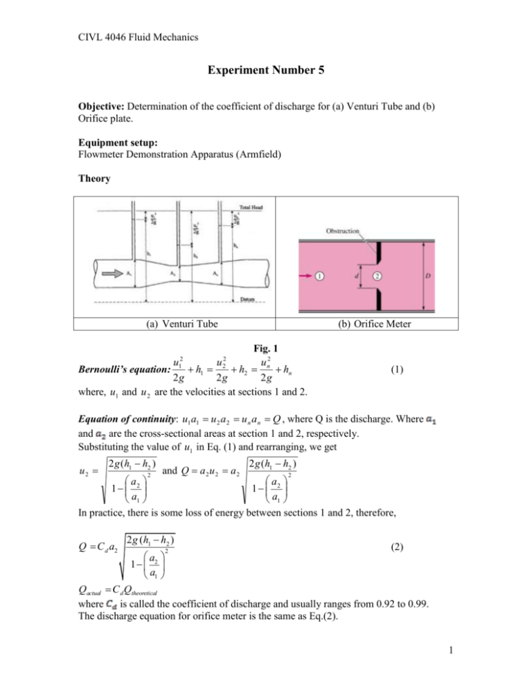
CIVL 4046 Fluid Mechanics Experiment Number 5 Objective: Determination of the coefficient of discharge for (a) Venturi Tube and (b) Orifice plate. Equipment setup: Flowmeter Demonstration Apparatus (Armfield) Theory (a) Venturi Tube (b) Orifice Meter Fig. 1 u n2 u u Bernoulli’s equation: h1 h2 hn 2g 2g 2g where, u1 and u 2 are the velocities at sections 1 and 2. 2 1 2 2 (1) Equation of continuity: u1a1 u 2 a 2 u n a n Q , where Q is the discharge. Where and are the cross-sectional areas at section 1 and 2, respectively. Substituting the value of u1 in Eq. (1) and rearranging, we get u2 2 g (h1 h2 ) 2 and Q a 2 u 2 a 2 2 g (h1 h2 ) 2 a a 1 2 1 2 a1 a1 In practice, there is some loss of energy between sections 1 and 2, therefore, Q C d a2 2 g (h1 h2 ) (2) 2 a2 1 a1 Qactual C d Qtheoretical where is called the coefficient of discharge and usually ranges from 0.92 to 0.99. The discharge equation for orifice meter is the same as Eq.(2). 1 CIVL 4046 Fluid Mechanics Results and Calculations: (a) Venturi Tube Data Diameter of the pipe at section 1: Diameter of the pipe at section 2: Table 1. Measurements and Calculations for Venturi Tube Volume Time Qactual h1 h2 Qtheoretical 3 (L) (s) (m /s) (m3/s) (m) Cd (b) Orifice Meter Data Diameter of the pipe at section 1: Diameter of the orifice at section 2: Table 2. Measurements and Calculations for Orifice Meter Volume Time Qactual h1 h2 Qtheoretical (L) (s) (m3/s) (m3/s) (m) Cd Format for the report The following sections must be included in the laboratory report Objective, Equipment setup, Theory Readings and calculations Graphs for both the devices (Qactual versus Qtheoretical and Cd vs Qactual) Comments on the results 2
