Steel Building Design Project: Structural Analysis & Optimization
advertisement
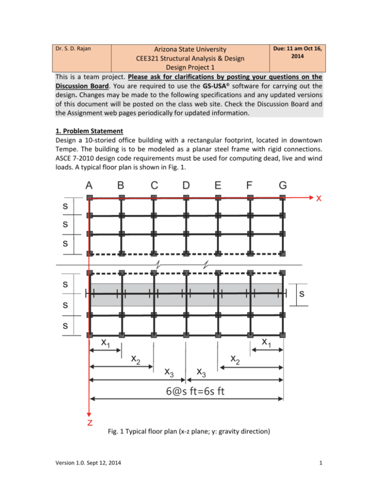
Dr. S. D. Rajan Due: 11 am Oct 16, Arizona State University 2014 CEE321 Structural Analysis & Design Design Project 1 This is a team project. Please ask for clarifications by posting your questions on the Discussion Board. You are required to use the GS-USA© software for carrying out the design. Changes may be made to the following specifications and any updated versions of this document will be posted on the class web site. Check the Discussion Board and the Assignment web pages periodically for updated information. 1. Problem Statement Design a 10-storied office building with a rectangular footprint, located in downtown Tempe. The building is to be modeled as a planar steel frame with rigid connections. ASCE 7-2010 design code requirements must be used for computing dead, live and wind loads. A typical floor plan is shown in Fig. 1. A B C D E F G x s s s s s s s x1 x1 x2 x2 x3 x3 6@s ft=6s ft z Fig. 1 Typical floor plan (x-z plane; y: gravity direction) Version 1.0. Sept 12, 2014 1 The planar frame that is to be designed is the shaded frame shown in Fig. 1. Note that s is the spacing between the frames. 2. Design Objective Minimize the cost of the structure, while satisfying all of the specifications listed below. 3. Building Configuration a. Take the total span of the typical frame as 120 ft, i.e. 6s = 120 ft. b. All connections are rigid connections. c. The height of the first floor containing the lobby is 16 ft. All the other floor heights are 13 ft. d. The floor system consists of 3” cellular steel deck with 2.5” concrete slab supported on the steel joists. e. Make sure that your model can be analyzed by the GS-USA Frame© program. GS-USA supports a maximum of 150 members and 50 design variables. f. Take the total number of frames in the z-direction as 15. g. All supports must be modeled as fixed supports. h. The spacing between adjacent columns cannot be less than 10 ft (note that this effects the values of x1 and x2). i. The building will primarily be leased by firms specializing in cloud computing with some space in some floors used for dining areas and restaurants. j. The roof is not earmarked for any special use. k. An example layout of the typical planar frame is shown in Fig. 2. 6@20’=120 ft 133 ft y x Fig. 2 Typical building frame Version 1.0. Sept 12, 2014 2 4. Member Properties a. Materials: The steel columns, beams and bracings of the building are assumed to be of grade A992/A992M. The floor slabs are assumed to be of high strength reinforced concrete. Material Table 1. Material Properties Structural element Material Property Steel, Grade Columns, beams, and A992/A992M bracings Concrete Slab Value Mass density 7.47 104 Elastic Modulus 2.9 104 ksi Yield stress 50000 psi Mass density 2.25 104 Poisson’s Ratio 0.15 Elastic Modulus 4.6 103 ksi slugs in3 slugs in3 b. Cross-Sections: The members of the structure are custom-made wide flange sections. With web height, hw , flange width, w f , web thickness, t w , and flange thickness, t f , the relationships between the four cross-sectional dimensions can be established as (units are inches) w f 0.235hw 7.12 (1) t f 0.492tw 0.106 (2) t f 0.0406w f 0.118 (3) It is recommended that you take the web height as the design variable for each different cross-section. The web and flange thicknesses cannot be less than 0.25 in. c. You may group the members appropriately in order to reduce the number of different cross sections and must justify how and why the grouping decision was taken. 5. Loads The building must be capable of safely carrying the following loads: a. Dead Loads: i. Weight of the cellular steel deck and reinforced concrete floor slab. ii. Self-weight of structure materials. iii. Ignore the weight of the transverse beams. iv. Use ASCE 7-2010. Version 1.0. Sept 12, 2014 3 b. Live Loads: i. Use ASCE 7-2010. 6. Loads and Load Combinations In Allowable Stress Design, the combinations of service loads are evaluated for maximum stresses and compared to allowable stresses. ASCE-7-2010 combinations of loads that must be used in the design project, are shown below. 1. LC 1: Dead load 2. LC 2: Dead load + Live load 3. LC 3: Dead load + 0.6 Wind Load 4. LC 4: Dead load + 0.75 Live Load + 0.75(0.6 Wind Load) 7. Structural Safety The building will comply with the following structural requirements ( f y is the yield stress of steel). a. Tensile stress cannot exceed 0.6 f y . b. Compressive stress cannot exceed 0.6 f y . c. Shear stress cannot exceed 0.4 f y . d. Euler buckling must be satisfied with a safety factor 2.0. e. Horizontal deflection cannot exceed H/500 where H is the total height of the building. 8. Cost The cost of the design will be calculated using the following cost factors: a. Material Cost: $0.50 per kilogram. b. Connection Cost: $500 + $20 x m (# of members at joint) per joint. c. Product Cost: $500 per product (this is not per element) i. In real structural design and construction, the most economical design is often not the one that simply minimizes the material cost. Often standardizing the materials and member sizes can reduce the total cost of the structure. If all the members in a structure are different materials and sizes, then the cost of ordering, fabricating, and constructing those members will be relatively high. If many members are the same, fabrication and construction costs will be relatively lower. ii. If the structure uses only one cross sectional area then the product cost is $500 for the entire structure. If the structure uses only two different types of cross sectional areas then the product cost is $1000 for the entire structure. This accommodates for additional manufacturing expenses. Further penalties and expenses would be expected if more Version 1.0. Sept 12, 2014 4 than one steel material is used, however this problem clearly defines that only one steel material is to be used. NOTE: Multiply the final calculations in parts a, b, and c by 15, which is the total number of planar frames in the building. Report the final cost calculations using the style shown in Table 2. Adjust the style and contents, if necessary, for your particular design. Item Material cost Connection cost Table 2. Summary of Final Cost Calculations Quantity per frame Unit cost Product cost TOTAL BUILDING COST 15 SUM $mno/frame Cost per frame $abc $def $ghi $mno $PQR=(15)(mno) 9. Report Format (1) Title Page. (2) Table of Contents. (3) Group Work Log. This should contain a sufficiently detailed log of your group as well as individual activities – who did what, when and about how long. If and when there are problems with a group, it is the responsibility of each individual to bring this to my attention as quickly as possible. (4) Design Problem Statement. (5) Problem Data and Assumptions (including limitations) (i) With respect to structural analysis. (ii) With respect to design requirements. (iii) Tools used for analysis and design. Make a checklist of all the different checks that needs to be made to ensure that the design is a valid design. (6) Initial Design. Explain your choice of initial design. Show what you checked by hand to ensure that the initial design made sense. (7) Details of Design Iterations. Explain your strategy in making the design changes. (8) Final Design. The final design must be checked against GS-USA computer output. The final design results must also be checked by hand. (9) Turn in an electronic version as a MS Word file. In a zip file put in all the GS-USA files. Create subdirectories called Initial Design, Intermediate Designs, and Final Design. The subdirectories Initial Design and Final Design should have one and only one GS-USA file corresponding to the initial and final design, respectively. e-mail the electronic files to the TA. Version 1.0. Sept 12, 2014 5 Requirements (i) The Group Work Log must be signed by all members of the group. (ii) Draw legible figures. Relevant figures must be drawn using AUTOCAD. (iii) Use tables to represent information. (iv) Must show all hand calculations, computer program listings, and computer program output, whenever applicable. (v) The analysis of the initial and final designs must be done using GS-USA© program. There is no requirement that you use the design features of the GS-USA© program. However, the initial and final designs must be analyzed and checked by the GS-USA© program. (vi) Send me via e-mail, peer assessment (of the other members in your group) within 24 hours of turning in your group report. Grading Procedure (i) Report ...................................................................................................................25% (ii) Choice of tools and procedures used ...................................................................15% (iii) Assumptions are reasonable and design meets requirements ...........................40% (iii) Scaled score with respect to the best design ......................................................20% (iv) Bonus points will be given for generating the model using a MATLAB code. Please see me for details. Version 1.0. Sept 12, 2014 6

![Structural Applications [Opens in New Window]](http://s3.studylib.net/store/data/006687524_1-fbd3223409586820152883579cf5f0de-300x300.png)
