notes05
advertisement
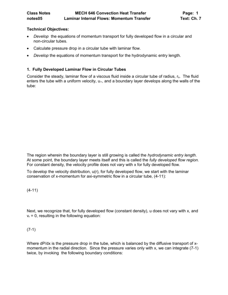
Class Notes notes05 MECH 646 Convection Heat Transfer Laminar Internal Flows: Momentum Transfer Page: 1 Text: Ch. 7 Technical Objectives: Develop the equations of momentum transport for fully developed flow in a circular and non-circular tubes. Calculate pressure drop in a circular tube with laminar flow. Develop the equations of momentum transport for the hydrodynamic entry length. 1. Fully Developed Laminar Flow in Circular Tubes Consider the steady, laminar flow of a viscous fluid inside a circular tube of radius, rs. The fluid enters the tube with a uniform velocity, u∞, and a boundary layer develops along the walls of the tube: The region wherein the boundary layer is still growing is called the hydrodynamic entry length. At some point, the boundary layer meets itself and this is called the fully developed flow region. For constant density, the velocity profile does not vary with x for fully developed flow. To develop the velocity distribution, u(r), for fully developed flow, we start with the laminar conservation of x-momentum for axi-symmetric flow in a circular tube, (4-11): (4-11) Next, we recognize that, for fully developed flow (constant density), u does not vary with x, and vr = 0, resulting in the following equation: (7-1) Where dP/dx is the pressure drop in the tube, which is balanced by the diffusive transport of xmomentum in the radial direction. Since the pressure varies only with x, we can integrate (7-1) twice, by invoking the following boundary conditions: Class Notes notes05 MECH 646 Convection Heat Transfer Laminar Internal Flows: Momentum Transfer Page: 2 Text: Ch. 7 Integrating once yields: (7-2a) Invoking the boundary condition for the derivative of u(r) at r =0 yields: Integrating a second time yields: Invoking the no slip condition at the surface of the tube yields: (7-2) which is the familiar parabolic velocity distribution for fully developed flow in a circular tube. Recognizing that we can define the average velocity as follows: Class Notes notes05 MECH 646 Convection Heat Transfer Laminar Internal Flows: Momentum Transfer Page: 3 Text: Ch. 7 (7-6) We can substitute (7-2) into (7-6), yielding: (7-7) And, combining (7-7) with (7-2), yields the following equation for the velocity profile: (7-8) Next, we can evaluate the shear stress at the surface. Recall, equation (7-2a), with the integration constant c1 having been evaluated to be zero: Using the definition of shear stress at the surface, results in the following relationship between wall shear stress and pressure drop in the tube: (7-11) Next, we can evaluate the wall shear stress by taking the derivative of equation (7-8) at r = rs: (7-9) Class Notes notes05 MECH 646 Convection Heat Transfer Laminar Internal Flows: Momentum Transfer Page: 4 Text: Ch. 7 Defining a non-dimensional friction coefficient with respect to the average velocity: (7-13) Substituting (7-9) into (7-13) yields: And recognizing that the Reynolds number is defined as: Results in the following equation for friction coefficient for laminar flow in a circular tube: (7-15) Finally, we can develop the equation for pressure drop in a circular tube with laminar flow: Class Notes notes05 MECH 646 Convection Heat Transfer Laminar Internal Flows: Momentum Transfer Page: 5 Text: Ch. 7 Example 6.1. To create small droplets of biodiesel, a fuel feed system is being designed that consists of a syringe pump to force the liquid biodiesel fuel through a 3 inch long section of hypodermic tubing with an inner diameter of 0.009 inches. The flow rate required is 5 ml/hr. The syringe has an inner diameter of 0.75”. Calculate the force required on the syringe. Class Notes notes05 MECH 646 Convection Heat Transfer Laminar Internal Flows: Momentum Transfer Page: 6 Text: Ch. 7 2. Fully Developed Laminar Flow for Non-Circular Tubes Equation (7-1) is only valid for circular tubes because it was developed in cylindrical coordinates. For non-circular tubes, a slightly more general form of the steady, incompressible x-momentum equation must be solved : (7-16) Where: With the assumption that dP/dx is constant over the entire cross section of the non-circular tube, it is possible to solve equation (7-16) numerically for a variety of shapes. Figures 7-4 and 7-5 in your book contain curves for friction coefficient, Cf, as a function of various rectangular aspect ratios and for flow in a circular annulus, respectively: After evaluating the friction coefficient, CF, from Figs, 7-4 and 7-5, the pressure drop, dP/dx can be calculated from (7-15a). Note that the Reynolds number in this case is based on the hydraulic diameter: (7-17) Where the hydraulic diameter is defined as: (7-17a) Where A is the cross sectional area and P is the perimeter. Class Notes notes05 MECH 646 Convection Heat Transfer Laminar Internal Flows: Momentum Transfer Page: 7 Text: Ch. 7 3. The Laminar Hydrodynamic Entry Length We now return to the entry length of the tube, wherein the boundary layers are still developing along the walls of the tube. In this case, u= u(x,r) and vr is not equal to zero and the following form of the x-momentum equation must be solved: (7-18) with the following boundary conditions: By solving equation (7-18) numerically, subject to the above boundary conditions, it is possible to solve for the velocity profiles u(r,x) as a function of x as shown in Fig 7-6: To solve for the pressure drop in the entry length, it is easier to consider an integral control volume approach. Consider the following control volume: Class Notes notes05 MECH 646 Convection Heat Transfer Laminar Internal Flows: Momentum Transfer Page: 8 Text: Ch. 7 Conservation of x-momentum requires that: (7-19a) Substituting in for the momentum flux entering and exiting the control volume, and simplifying, yields: (7-19b) Dividing through by dx yields: (7-19c) Where it must be noted that dA is the differential of the cross sectional area A, and dAs is the differential of the surface area of the tube. Equation (7-19c) can be integrated from the inlet, where u= V, to some arbitrary location x2: (7-19d) As was done for the fully developed flow condition, we can define a local friction coefficient based on the inlet velocity, V: Class Notes notes05 MECH 646 Convection Heat Transfer Laminar Internal Flows: Momentum Transfer Substituting in for CF yields: (7-19e) Which, after dividing through by V2, becomes: (7-19) Where a mean friction coefficient has been defined as follows: (7-20) Homework: 7-1, 7-2 (constant density only), 7-7 Due Date: Page: 9 Text: Ch. 7
